Testing Calibration and Relays
Entek IRD 6666 and 6667 Protection Monitors
47
4.
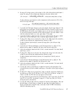
If using a DC voltage source, set the voltage to 50% of the full scale for input channel 1,
minus the voltage for the cold junction temperature from the table in step 3.
If using a thermocouple simulator, set the temperature on the simulator to 50% of the
full scale for input channel 1.
5.
Look at the 6667 front panel display, and note the digital value for input channel 1. The
digital value for input channel 1 should be half of full scale. It might be easiest to press
the DIS button to choose the second display page so you can see every channel at once.
If you use the bar graph, remember that the monitor displays the input channel 1 value
when the indicator (a dash) is over the input channel 1 bar graph.
6.
Look at the multimeter attached to the 4–20 mA recorder terminals. The meter should
read 12 mA ± 4.5% of full scale. 12 mA is half the range between 4 and 20.
7.
If using a DC voltage source, increase the voltage to the voltage high value, minus the
voltage for the cold junction temperature from the table in step 3.
If using a thermocouple simulator, increase the temperature to the full scale high
temperature.
8.
Look at the 6667 front panel display, and note the digital value for channel 1. The
digital value for channel 1 should be the same as the full scale high value.
9.
Look at the multimeter attached to the 4–20 mA recorder terminals. The meter should
read 20 mA ± 4.5%.
10. If using a DC voltage source, decrease the voltage to the voltage low value minus the
voltage for the cold junction temperature from the table in step 3.
If using a thermocouple simulator, decrease the temperature to the full scale low
temperature.
11. Look at the 6667 front panel display, and note the digital value for channel 1. The
digital value for channel 1 should be the full scale low value.
12. Look at the multimeter attached to the 4–20 mA recorder terminals. The meter should
read 4 mA ± 4.5% of full scale.
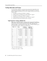
13. Test the state of the System OK relay terminals (25 and 26 on the backplane). The
System OK relay is always in failsafe condition, so it should be in the energized (Open)
position.
14. If using a DC voltage source, increase the voltage so that the temperature displayed on
the monitor goes above the TX HI limit (“TX 1-3 and TX 4-6 submenus” on page 21).
Check to see that the TX FAIL message appears on the monitor.
If using a thermocouple simulator, increase temperature so that it goes above the TX HI
limit (“TX 1-3 and TX 4-6 submenus” on page 21). Check to see that the TX FAIL
message appears on the monitor.
15. Test the state of the System OK relay terminals (25 and 26 on the backplane). The state
should change to Closed when you change the input signal, indicating transducer
failure. Note that the System OK relay is not subject to the GLOBAL alarm delay
(DELAYS submenu, page 25).
50% full scale
voltage high
voltage low
+
2
--------------------------------------------------------------------
cold junction temperature voltage
–
=
50% full scale
full scale high temperature
full scale low temperature
+
2
-------------------------------------------------------------------------------------------------------------------------------------
=


