background image

SERVICE

Manual

LCD Monitor

Fashion Feature

LCD-Monitor

Chassis

Model

LME20WS 206BW

LME22WS 226BW

LME20AS

206NW

LME22AS

226NW

LME22VS

216BW

223BW

- Magic Bright

- Magic Color

- Integrated UI applied

- Hidden Function Key

- Lustrous Appearance (Design)

Summary of Contents for LME20WS

Page 1: ...onitor Fashion Feature LCD Monitor Chassis Model LME20WS 206BW LME22WS 226BW LME20AS 206NW LME22AS 226NW LME22VS 216BW 223BW Magic Bright Magic Color Integrated UI applied Hidden Function Key Lustrous...

Page 2: ...Samsung Electronics Co Ltd LME20WS LME22WS LME20AS LME22AS LME22VS Service Manual First edition December 2006 Printed in Korea Trademarks Samsung is the registered trademark of Samsung Electronics Co...

Page 3: ...22VS Specifications 2 6 2 8 Spec Comparison 2 7 2 9 Option Specification 2 8 3 3 Alignments and Adjustments 3 3 1 3 1 Required Equipment 3 1 3 2 Automatic Color Adjustment 3 1 3 3 DDC EDID Data Input...

Page 4: ...3 Using the Stand 10 4 1 11 Disassembly and Reassembly 1 11 1 11 1 Disassembly 11 1 11 2 Reassembly 11 3 1 12 PCB Diagram 1 12 1 13 C Circuit Descriptions 1 13 1 13 1 Block description 13 1 13 2 Bloc...

Page 5: ...City Gyeonggi Do Korea 443 742 Printed in Korea P N BN82 00138M 03 URL http itself sec samsung co kr This Service Manual is a property of Samsung Electronics Co Ltd Any unauthorized use of Manual can...

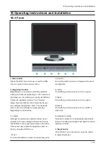
Page 6: ...buttons 1 Custom Although the values are carefully chosen by our engineers the pre configured values may not be comfortable to your eyes depending on your taste If this is the case adjust the brightn...

Page 7: ...ter Auto adjustment allows the monitor to self adjust to the incoming video signal The values of fine coarse and posi tion are adjusted automatically Available in ana log mode only 6 Power button Use...

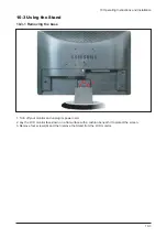
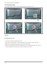
Page 8: ...g the Stand 10 3 1 Removing the base 1 Turn off your monitor and unplug its power cord 2 Lay the LCD monitor face down on a flat surface with a cushion beneath it to protect the screen 3 Remove four s...

Page 9: ...ushion beneath it to protect the screen 3 Remove four screws and then remove the stand from the LCD monitor 4 Align the mounting interface Pad with the holes in the rear cover mounting pad and secure...

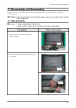
Page 10: ...tors WARNING This monitor contains electrostatically sensitive devices Use caution when handling these components 11 1 Disassembly Cautions 1 Disassembly stand on the flat desk 2 Disconnect the monito...

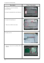
Page 11: ...re Description 4 Use the jig to remove the shield lamp Be careful Shield 5 Remove the FUNCTION Wire from PCB ASS Y 6 Remove the Panel Lamp wire 7 Remove the LVDS Wire from Panel 8 Remove 4 screws 9 Re...

Page 12: ...11 Disassembly and Reassembly 11 3 10 Main PCB and IB Board Description Picture Description...

Page 13: ...11 Disassembly and Reassembly 11 4 11 2 Reassembly Reassembly procedures are in the reverse order of disassembly procedures...

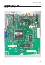
Page 14: ...13 Circuit Descriptions 13 1 13 Circuit Descriptions 13 1 Block description SDRAM Memory scaler Flash memory EEPROM EEPROM FET Array...

Page 15: ...13 Circuit Descriptions 13 2 Memo...

Page 16: ...ine and Coarse FINE Fine adjustment is used to adjust visibility by control phase difference COARSE This is a adjustment by tuning with Video colck and PLL clock DVI Digital Visual Interface This prov...

Page 17: ...sed for the majority of monitors to ensure a clear image The Interlace method is the same as that used in TVs Plug Play This is a function that provides the best quality screen for the user by allowin...

Page 18: ...to the DVI port on the back of your monitor 2 3 Connected to a Macintosh Connect the monitor to the Macintosh computer using the D SUB connection cable 3 Turn on your computer and monitor If your moni...

Page 19: ...wer Input 5V Self Raster GND Bi Dr Data SDA H V Sync Not Used DDC Clock SCL Red Green H V Sync Blue GND DDC Return GND GND R GND G GND B DDC Power Input 5V Self Raster GND Bi Dr Data SDA Not Used Not...

Page 20: ...rk IBM 640 75 Hz 640x480 800 60 Hz 800x600 800 75 Hz 800x600 1024 60 Hz 1024x768 1024 75 Hz 1024x768 VGA2 70 Hz 720 x 400 VGA3 60 Hz 640 x 480 Table 14 1 Timing Chart 31 469 31 778 3 813 1 589 26 058...

Page 21: ...x 1024 63 981 60 020 108 00 VESA 1280 x 1024 79 976 75 025 135 00 VESA 1600 x 1200 75 000 60 000 162 00 If the signal transferred from the computer is the same as the following Preset Timing Modes th...

Page 22: ...EW Color coordinates change for LCD TV SEC LTM153W1 L01 BN07 00092A EX AMLCD WIDE 15 9 10 SEC LTM170W1 L01 BN07 00100A EY Color Coordinates change code management SEC LTM170EH L05 BN07 00097A EZ LTM1...

Page 23: ...L11 BN07 00239A SPZ AMLCD 26 16 9 7Line new Panel SEC LTA400WS LH1 BN07 00245A SPZ AMLCD 40 16 9 SPVA 90 new Panel SEC LTM213U6 L01 BN07 00231A SPZ AMLCD 21 3 PVA new Panel Code SEC LTA320WS LH2 BN07...

Page 24: ...rivation ZPD ACER M170EN06 BN07 00171A ATH AU Monitor 17 New panel development ACER T260XW01 BN07 00163A AMZ AU 26 new panel development NF26EO ACER A201SN01 BN07 00177A ATZ AU TV panel 20 1 TN SVGA n...

Page 25: ...Memo 14 Reference Infomation 14 10...

Page 26: ...ntrast to 0 Then press the Enter Source key for 5 second Service function OSD will appear on screen 2 Press the key to place the cursor on the panel Press the menu key for 5 seconds 3 5 OSD Adjustment...

Page 27: ...Upper lamp on time When the upper lamp is replaced press menu to add to the Ch No which shows the number of times the lamp has been replaced 5 Lower lamp lower lamp on time When the upper lamp is repl...

Page 28: ...shing then all menus return to the factory default 3 Auto calibration To Analog video In 16gray or any pattern using black and white and any mode 16gray and XGA mode recommend 1 Push the OSD Menu butt...

Page 29: ...rogram 1 Winddc exe Program install in PC 2 Cilck the Winddc icon 3 File open 4 Select Port 1 Load DDC fileFile Name 206BW ddc Click Next OK button After change a Main Board DDC input shpuld be done v...

Page 30: ...tems after replacing the main board After Replacing the Maing Board 1 Auto Calibration 2 EDID installation Analog and Digital 3 Factory Reset 5 Input a monitor serial number and push the enter key Aft...

Page 31: ...Memo 3 Alignments and Adjustments 3 6...

Page 32: ...700 Check the IP Board There is no light in the power indicator Check IC310 Yes No Does proper DC 5V appear at Output of C719 Check the IC702 Yes No Does proper DC 3 3V appear at Pin 4 of the IC705 Ch...

Page 33: ...4 Troubleshooting 4 2 WAVEFORMS 2 1 3 4...

Page 34: ...o Video PC Analog Signal 5 Check TFT_LCD panel or inverter and connection between then Yes No Does the analog video signal appear at R104 R105 R106 Red Green Blue Check pc signal Yes No Does the X710...

Page 35: ...4 Troubleshooting 4 4 WAVEFORMS 6 5 7...

Page 36: ...Pin9 of CN700 BKLT_EN high 3 3V 4 3 No Video PC Digital Signal 1 Check TFT_LCD panel or inverter and connection between then Yes No Does the Digital video signal appear at R200 R227 Check PC signal Ye...

Page 37: ...4 Troubleshooting 4 6 WAVEFORMS 9 5...

Page 38: ...4 Troubleshooting 4 7...

Page 39: ...4 Troubleshooting 4 8...

Page 40: ...4 Troubleshooting 4 9...

Page 41: ...Memo 4 Troubleshooting 4 10...

Page 42: ...0mm 1 S A 2 M0125 BN39 00246F CBF SIGNAL DVI D 1703FP 24P 24P 20276 D 1 S A 2 M0027 BN96 04541A ASSY STAND P BASE LS20MEW ABS HB BK26 BK 1 S A 3 M0081 6003 001001 SCREW TAPTITE FH B M3 L8 ZPC BLK SWRC...

Page 43: ...6 Electrical Parts List 6 2 Memo...

Page 44: ...7 Block Diagrams 7 1 7 Block Diagram 7 1 Block Diagram...

Page 45: ...7 Block Diagrams 7 2 Memo...

Page 46: ...9 Schematic Diagrams 9 1 9 Schematic Diagrams This Document can not be used without Samsung s authorization 9 1 Schematic Diagrams...

Page 47: ...9 Schematic Diagrams 9 2 This Document can not be used without Samsung s authorization...

Page 48: ...9 Schematic Diagrams 9 3 This Document can not be used without Samsung s authorization...

Page 49: ...9 Schematic Diagrams 9 4 Memo...

Page 50: ...ew Parts List 5 1 5 Exploded View and Parts List You can search for updated part codes through ITSELF web site URL http itself sec samsung co kr 5 1 LS22MEVSFV EDC Exploded View M0215 M0013 M0006 M000...

Page 51: ...CD PANEL CLAA220WA01 Mendel 6bit Hi FRC 1 S A M0013 BN96 04544B ASSY COVER P REAR LS22MEV HIPS HB BK07 1 S A M0006 BN63 02915A COVER REAR LS22MEW HIPS HB BK07 1 S N A M0113 BN61 02806A BRACKET VESA LS...

Page 52: ...9 Schematic Diagrams 9 1 9 Schematic Diagrams This Document can not be used without Samsung s authorization 9 1 Schematic Diagrams...

Page 53: ...9 Schematic Diagrams 9 2 This Document can not be used without Samsung s authorization...

Page 54: ...9 Schematic Diagrams 9 3 This Document can not be used without Samsung s authorization...

Page 55: ...9 Schematic Diagrams 9 4 Memo...

Reviews: