Configuration
Entek IRD 6666 and 6667 Protection Monitors
21
TX 1-3 and TX 4-6 submenus
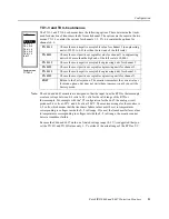
The TX 1-3 and TX 4-6 submenus have the following options. These determine the limits
used for detection of transducer faults for each channel. The options are the same in the two
menus. TX 1-3 contains the options for channels 1–3. TX 4-6 contains the options for
channels 4–6.
Note: The 6666 and 6667 monitors are designed so that the input from the RTD or thermocouple
creates a voltage between 0.4 volts to 4.8 volts for the valid range of the RTD or
thermocouple. For example with the “B” configuration for the 6667, the analog circuit
produces 0.4 volts at -20°C and 4.8 volts at 200°C. The maximum range for the monitor is
0–5 volts, which means that the transducer failure values must be set to temperatures
corresponding to voltages inside the 0–5 volt range. If you set the transducer failure values
to temperatures corresponding to voltages outside the 0–5 volt range, the monitor cannot
detect a transducer failure.
Because the 6666 and 6667 work on a limited voltage range (0–5 V) is suggested that you
set the TX LO and TX HI values only 1–5° outside of the actual range of the RTD or T/C.
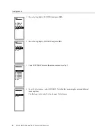
TX H1
1
TX LO
2
TX HI 2
TX LO
3
TX HI 3
EXIT
TX LO 1
SET
Factory menu
→
TX 1-3
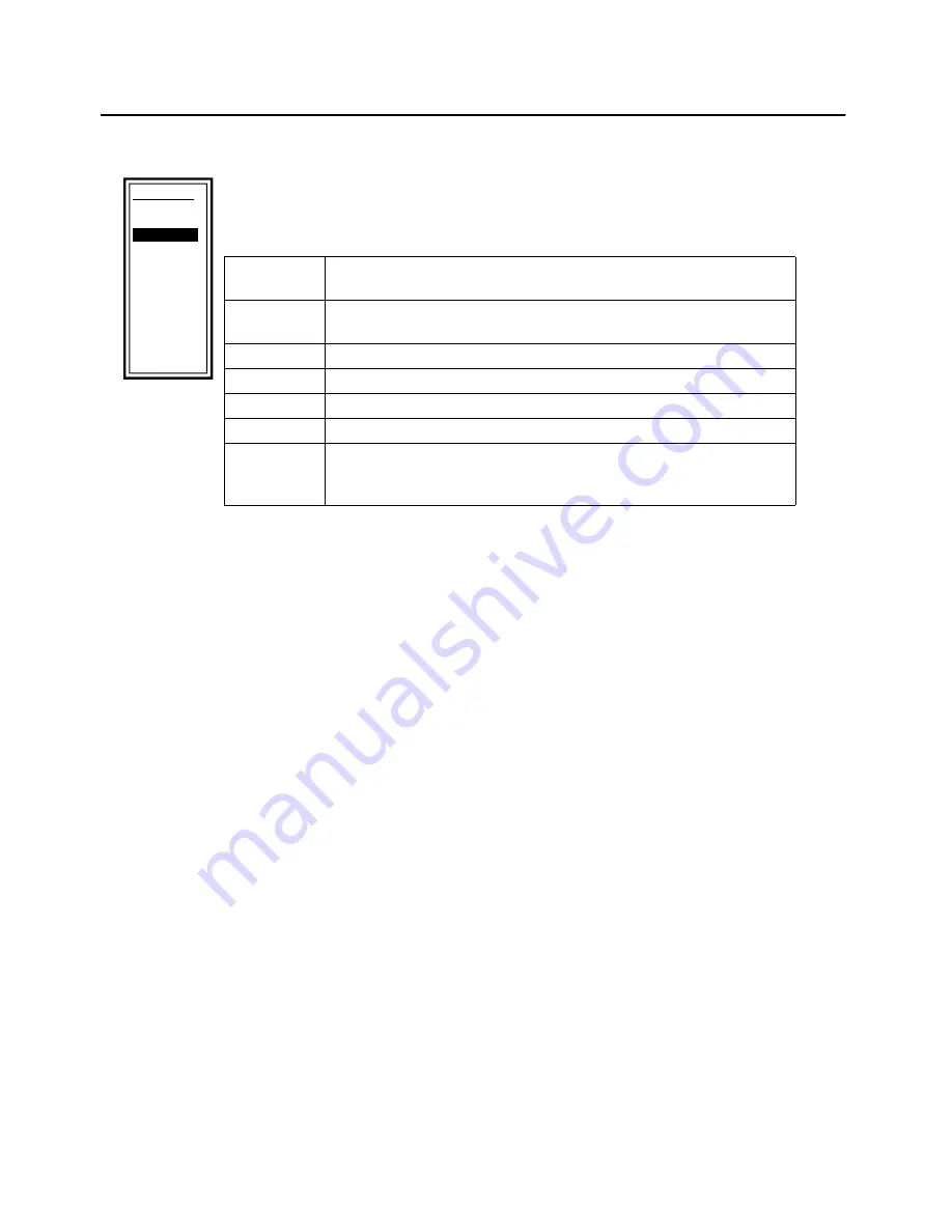
TX LO 1
Choose the most negative acceptable value for channel 1 in engineering
units (-999.99 to 0.01 less than the low end of the full scale).
TX HI 1
Choose the most positive acceptable value for channel 1 in engineering
units (0.01 more than the high end of the full scale to 10,000).
TX LO 2
Choose the most negative acceptable engineering units for channel 2.
TX HI 2
Choose the most positive acceptable engineering units for channel 2.
TX LO 3
Choose the most negative acceptable engineering units for channel 3.
TX HI 3
Choose the most positive acceptable engineering units for channel 3.
EXIT
Return to the Factory menu. The monitor remembers the current values
for menu options, but does not write them to memory until you exit the
Factory menu.

