50
Entek IRD 6666 and 6667 Protection Monitors
Testing Calibration and Relays
1.
Connect a known resistance (6666), DC voltage source (6667), or thermocouple
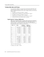
simulator (6667) to the channel 1 input terminals. Refer to “Signal Inputs for Testing a
6666 Monitor” on page 40 and “Signal Inputs for Testing a 6667 Monitor” on page 43
for details.
2.
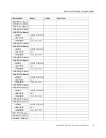
Connect a multimeter to the channel 1 Alert relay terminals to test for continuity (25
and 26 on the backplane). You could also connect to the channel 1 relay N/O instead of
the N/C terminal (26 and 27 on the backplane).
3.
Set the resistance, DC voltage, or thermocouple simulator so that the temperature
displayed on the monitor for channel 1 is less than the Alert setpoint for channel 1. This
is the ALERT 1 option on the ALM 1-3 submenu (page 17). Remember that the
monitor displays the input channel 1 value when the indicator (a dash) is over the input
channel 1 bar graph.
Note:
The following steps assume you set RISING to YES (“RISING submenu” on page 25).
If you set RISING to NO, start with the displayed temperature above the Alert setpoint,
and decrease the input to trigger the alarm.
4.
If the LATCHED option is set to YES, you may have to manually reset the relays by
pressing the RES button on the front panel of the monitor.
5.
Test the state of the Channel 1 Alert relay terminals (open or closed). Remember that
under standard mapping, all Alert alarms use the first relay.
6.
Increase the resistance, DC voltage, or thermocouple simulator temperature so that the
displayed temperature exceeds the channel 1 Alert setpoint.
7.
Test the state of the channel 1 Alert relay terminals. The state should change when the
input signal exceeds the Alert setpoint. Depending on the GLOBAL option setting in
the DELAYS submenu (page 25), it may take up to 30 seconds before the relay changes
state.
8.
Test the state of the channel 1 Danger relay terminals (open or closed).
9.
Increase the resistance, DC voltage, or thermocouple simulator temperature to exceed
the channel 1 Danger setpoint so that the displayed temperature exceeds the channel 1
Danger setpoint.
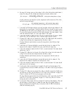
10. Test the state of the channel 1 Danger relay terminals on the backplane. The state
should change when the input voltage exceeds the Danger setpoint. Depending on the
GLOBAL option setting in the DELAYS submenu (page 25), it may take up to 30
seconds before the relay changes state.
Repeat this process to test the other five Danger alarm relays (for standard mapping).


