Testing Calibration and Relays
Entek IRD 6666 and 6667 Protection Monitors
41
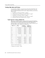
The analog circuitry of the 6666 produces a voltage between 0.4 volts to 4.8 volts for each
of the resistance ranges in the table above. For example, for suffix “B”, the analog circuit
produces 0.4 volts at -20°C and 4.8 volts at 200°C. The maximum range for the monitor is
0–5 volts, which means that the transducer failure values must be set to temperatures
corresponding to voltages inside the 0–5 volt range (“TX 1-3 and TX 4-6 submenus” on
page 21). If you set the transducer failure values to temperatures corresponding to voltages
outside the 0–5 volt range, the monitor cannot detect a transducer failure.
This example assumes that the 6666 has a “C” configuration on channel 1.
Example:
Configuration type
“C”
Full scale low
0°C (100.00 ohms)
Full scale high
250°C (194.07 ohms)
TX LO
-5°C
TX HI
255°C
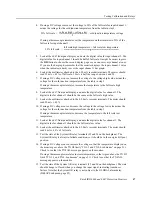
Note:
The sensitivity and full scale are set at the factory and cannot be changed. You can find
the sensitivity with the following equation.
For the “C” configuration:
Refer to the following diagram for the correct connections between the monitor and the
testing equipment. This diagram shows the typical signal inputs and connections for testing
6666 monitors.
sensitivity
resistance high
resistance low
–
full scale high temperature
full scale low temperature
–
------------------------------------------------------------------------------------------------------------------------------------
=
sensitivity
194.07 ohms
100 ohms
–
250°C
0°C
–
------------------------------------------------------------
0.3763 ohms/°C
=
=
TYPIC AL SIGN AL INPUTS FOR TESTING
666 6 SIX CHA NNEL PROC ESS M ON ITOR
1 ( C H A N 1 HI )
NO TE : T H E S E I NP UT S A R E
L O C A TE D O N T H E T E R M I N A L
B L O C K
V A R I A B LE RE S I S T A N C E
2 ( C H A N 1 L O 1 )
3 ( C H A N 1 L O 2 )


