background image

41

Scan Types

There are four scan types:

• 

Spectral Scan:

 measures and displays the maximum amplitude vs. frequency of the magnetic field 

strength over the scanned area.

• 

Spatial Scan:

  measures  the  magnetic  field  of  radiated  electromagnetic  emissions  from  the 

DUT at a single frequency as a function of position. It can be a single scan or interleaved scan.  

Interleaved Scan 

is meant to overcome the limitations of the probe polarizations. By measuring a 

DUT twice with a small physical shift between the two scans this blind spot can be eliminated.

• 

Spectral / Spatial Scan: 

measures the magnetic field strength of radiated electromagnetic emissions 

from an object as a function of both frequency and position on the PCB. It collects a series of Spatial 
Scans over the entire frequency range of interest as opposed to a Spatial Scan (which gathers data 
at single frequency) or a Spectral Scan (which saves only the composite maximum data set over the 
scan area).

• 

Handheld Probe Scan: 

ERX+ | EHX+ allows use of a hand-held probe to achieve finer resolution. 

Handheld Probe Scan provides a method to easily collect and display data from sensors other than 
the ERX+ | EHX+ scanner. It is compatible with any sensor that the user wishes to use and that can 
be connected to a supported spectrum analyzer. You can carefully synchronize the positioning of the 
probe with the manual triggering and create high resolution spatial plots of the DUT.

There are four methods to further analyze the scanned data:

• 

Spectral Overlay:

 is a qualitative comparison of two frequency spectra. It superimposes one 

frequency spectrum over another.

• 

Compare Spectral:

 is a quantitative comparison between two frequency spectra. It is generated by 

subtracting the values of one spectrum from the values of the second spectrum at each frequency.

• 

Interleaved Scan:

 is meant to overcome the limitations of the probe polarizations. By measuring a 

DUT twice with a small physical shift between the two scans blind spots can be eliminated.

• 

Compare Spatial:

 is a quantitative comparison between two Spatial Scans that is generated by 

subtracting the values of the first scan from the values of the second scan cell by cell.

To run a scan:

1.  Place the PCB or other device under test (DUT) on the patented scanner

2.  Select the scan type on EMxpert software

3.  Run the scan

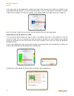
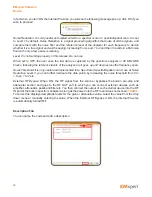
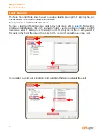
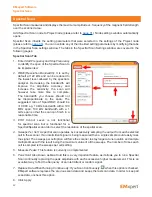
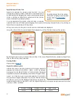
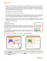
Power up the PCB or DUT and place it on the scanner aligning as closely as possible to the vertical and 
horizontal guidelines. Lining up with the squares assists you when importing overlays.

EMxpert Software

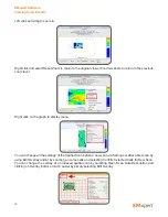
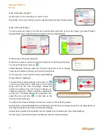
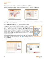
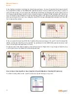
Scan Types

Placing PCB on EMSCAN’s patented scanner

Summary of Contents for EMxpert EHX+

Page 1: ...EMxpert ERX EHX User Manual v5 0 8 10 1 8 0 9 ...

Page 2: ...d fitness for a particular purpose EMSCAN shall not be liable for errors or for incidental or consequential damages in connection with the furnishing use or performance of this document or any information contained herein Should EMSCAN and the user have a separate written agreement with warranty terms covering the material in this document that conflict with these terms the warranty terms in the s...

Page 3: ...SCAN if Buyer is under warranty original or extended You can extend your original warranty by purchasing option 3000 1810 or 3000 1811 Additional One Year Customer Care Package Is your document and EMxpert software up to date Periodically we update the documents and EMxpert software You may access to the latest versions from below links User manual http www emscan com emxpert EMx_userManuals cfm T...

Page 4: ...dware Setup 20 Software Installation 21 Setup and Modes of Operation 24 Menu Bar 26 Quick Facts about Menu Bar 27 Viewing Scan Results 28 Spectral View 28 Spatial View 29 Nodes 31 How to Add a Node 31 How to Name a Node 31 How to View a Node 31 How to Delete a Node 32 How to Export Data 32 Preferences Display Options 32 Project Node Settings 32 Overlay Editor How to Superimpose Graphical Image of ...

Page 5: ...on 68 Measurement Tips 69 Scanning a PCB 69 Scanning a System Level Device 70 Appendix Frequently Asked Questions FAQ 71 Appendix Fuse Replacement 75 Appendix How to Update Firmware 76 Appendix Error Messages 79 Appendix Regulatory Compliance 81 Safety and Regulatory Information 81 FCC Class B Notice 82 CSA Certification 83 CE mark 83 Notes 84 Table of Contents ...

Page 6: ...t Phone Toll Free North America Only 1 877 367 2261 International 1 403 291 0313 ext 2 Fax 1 403 250 8786 E mail support emscan com Website www emscan com Address EMSCAN Corporation 1 1715 27th Avenue N E Calgary Alberta Canada T2E 7E1 The serial number is located at the bottom of the scanner Start EMxpert software and click to access to software and firmware versions Contact Information Serial Nu...

Page 7: ...tched array which provides an effective 3 75 mm resolution The system operates from 150 kHz to 4 GHz or 150 kHz to 8 GHz the upgrade from 4 GHz to 8 GHz is enabled with an optional software license key EHX is a self contained very near field scanning device which uses the EHX scanner along with a built in spectrum analyzer Simply connect the EHX into the PC with an Ethernet connection install the ...

Page 8: ...rnet cable It connects the PC laptop or desktop to the EHX built in spectrum analyzer and controller boards 5 EMxpert USB Drive includes the EMxpert software installation program and User Manual Customer Provided Components 1 PC Laptop Desktop must support a LAN 10 100 connection It runs the EMxpert software and receives data which it can display and manipulate immediately or store for future data...

Page 9: ...ed 10 dBm 4 RF Out port output directly from scanner You can connect external devices such as amplifier attenuator passband filter etc to condition the signal directly from the scanner before its input into the built in spectrum analyzer 5 Ethernet cable port 6 Universal power supply port 7 Fuse to provide protection against excess current Specs 3A 250V size 0 177 Dia x 0 570 L 4 50 mm x 14 48 mm ...

Page 10: ...nnects the PC laptop or desktop to the ERX built in spectrum analyzer and controller boards 4 EMxpert USB Drive includes the EMxpert software installation program and User Manual Customer Provided Components 1 PC Laptop Desktop must support a LAN 10 100 connection It runs the EMxpert software and receives data which it can display and manipulate immediately or store for future data presentation Ab...

Page 11: ...ed 10 dBm 4 RF Out port output directly from scanner You can connect external devices such as amplifier attenuator passband filter etc to condition the signal directly from the scanner before its input into the built in spectrum analyzer 5 Ethernet cable port 6 Universal power supply port 7 Fuse to provide protection against excess current Specs 3A 250V size 0 177 Dia x 0 570 L 4 50 mm x 14 48 mm ...

Page 12: ...d Freight to from EMSCAN factory not included unless unit under original or extended warranty 3000 1911 Calibration Assurance Plan for the EHX and ERX Return to EMSCAN 5 years Annual single calibration event included Freight to from EMSCAN factory not included unless unit under original or extended warranty 3000 0900 On Site customer training per day Cost of instructor s travel and accommodation a...

Page 13: ... supply and turn on the system Arrow 2 The system status light Arrow 3 should flash orange for up to 1 minute and then turn green For your ERX only you should hear the motors moving and see the scanner reposition itself before the LED turns green If the LED does not turn green after a few minutes or turns red cycle the power to the ERX EHX by turning it off and on again If the problem persists the...

Page 14: ...n should indicate that it has connected to the system by displaying the system IP 172 16 1 148 in the status bar at the bottom left of the window Try running a scan if it gets blocked in the middle and or you see an error message take a look at the Windows Event Viewer of your computer and search for the event log of the firewall application which will show if it has blocked something That is the ...

Page 15: ... a little less than 8000 MHz depending on the RBW it might even be less than 7950 MHz Setting the pre amp to Level 2 below 50 MHz may result in saturation Noise floor smoothing and decimation of the noise signals are available through the user controlled Noise Reduction level and the Noise Threshold level a Noise Reduction Level 2 is incorrect Do not use 3 Spectral Spatial Scans c w Interleaved Sc...

Page 16: ... Noise Threshold level a Noise Reduction Level 2 is incorrect Do not use 5 Spectral Comparison is fully supported 6 Spatial Comparison is fully supported 7 Spectral Overlay is fully supported 8 Report Generator is fully supported 9 Reset to factory default is enabled 10 Firmware Upgrades can be done over a Google Chrome never with Internet Explorer Unsupported Features 1 Spectral scan peak marking...

Page 17: ...W 122 kHz 22 ms RBW 976 kHz 20 ms To get the total scan time multiply by the number of cells and for high resolution also multiply by the scan level power of 2 Note that you can set multiple sweeps per cell to catch short bursts About EMxpert EMxpert ERX Limitations ...

Page 18: ... be between 0 15 MHz 50 MHz or 50 MHz 8000 MHz b Maximum frequency shown will be a little less than 8000 MHz depending on the RBW it might even be less than 7950 MHz Setting the pre amp to Level 2 below 50 MHz may result in saturation Noise floor smoothing and decimation of the noise signals are available through the user controlled Noise Reduction level and the Noise Threshold level a Noise Reduc...

Page 19: ...ware Upgrades can be done over a Google Chrome never with Internet Explorer Unsupported Features 1 Spectral scan peak marking not implemented yet No inherited peak list will be generated in child spatial scan 2 Internal attenuation not supported 3 Probe compensation is not supported yet for Far Field Application Speed Information 1 Spatial speed per cell Same above and below 50 MHz RBW 30 kHz 33 m...

Page 20: ... 3 should flash orange for up to 1 minute and then turn green For your ERX only you should hear the motors moving and see the scanner reposition itself before the LED turns green If the LED does not turn green after a few minutes or turns red then cycle the power to the ERX EHX by turning it off and on again If the problem persists then contact EMSCAN Getting Started Hardware Setup 2 1 3 ...

Page 21: ...elect the software folder and double click on Setup exe file 2 When you are prompted Do you want to allow the following program from an unknown publisher to make changes to this computer click Yes 3 Click Next 4 Click Next Getting Started Software Installation ...

Page 22: ...22 5 Select I Agree and click Next 6 The following screen will be displayed Getting Started Software Installation ...

Page 23: ...peated start the the EMxpert ERX EHX Software by clicking the icon on the Desktop 9 When the system status light turns green open the EMxpert ERX EHX application After a few moments the software application should indicate that it has connected to the system by displaying the system IP 172 16 1 148 in the status bar at the bottom left of the window Getting Started Software Installation ...

Page 24: ... Spectral Scan for the bandwidth of interest Run the Spectral Scan and analyze the test results If there is any ambient noise being displayed the EMxpert s comparison features will allow you to filter it from the actual DUT test results Modes of Operation 1 PCB testing smaller than the scan area Place the PCB directly anywhere on the grid of the scanner If there are tall components that prevent th...

Page 25: ...an be tested for emissions Place the DUT on the scanner and tape the cables on the scanner 4 System testing EMxpert will help detect any leakages from a system under test for both frequency and location EMxpert Software Setup and Modes of Operation ...

Page 26: ... a project Close a project Access to recent documents Quick Access Toolbar About EMxpert EMxpert Help Auto hide or pin the project view Spectral Overlay Module Node Spectral Spatial Scan Spectral Scan Buttons Spectral Comparison Report Generator Handheld Probe Spatial Comparison Spatial Scan Preferences Stop Scan Settings Scan Once Scan Continuously Buttons Icons Start a new project Open an existi...

Page 27: ... default Project View is pinned and displayed in the EMxpert software In order to maximize the space to view the scan results Project View can be hidden Click the pin icon to auto hide Project View Project View will be hidden and now you can maximize the scan window Spectral Spatial Scan windows automatically resizes to fit the screen To display Project View mouse over on Project View tab It will ...

Page 28: ...the checkmark boxes at the bottom of the graph Grid and Peaks can be hidden displayed Unit can be switched between dBuV and dBm Linear scale is the default settings of the graph Log Scale can be selected Peak and Scale Options are listed under View Options Left click and drag to zoom in Right click and select Reset Zoom to return to the original view or Previous Zoom to return to the previous zoom...

Page 29: ...f data smoothing in the image can be turned on off By sliding the Set Color Threshold on the right side of the graph you can increase or decrease the contrast to more clearly identify current loops and peak locations Peak and Scale Options are listed under View Options View can be changed to 3D by clicking on the check box You can rotate the 3D view by left clicking on the graph and moving the mou...

Page 30: ...ge all the settings of the Spatial Scan before a new scan via Settings or after a first scan by using Edit Overlay and or by zooming on some cells and selecting Confirm Selected Cells for New Scan You can change the overlay of an indexed spatial scan by selecting Open Scan Data Description and clicking on Overlay Editor or much easier by simply selecting Edit Overlay EMxpert Software Viewing Scan ...

Page 31: ...ted throughout the module tree only Modules can be used to store data for different revisions of the PCB Nodes that don t contain any data are light colored How to Add a Node To add a node either right click on the Project node click on Add Node and then select one of the scans or click on one of the icons on the side bar on the left of the Project node How to Name a Node To name a node open the S...

Page 32: ...the spatial display Project Node Settings To select Project Node settings either click on in the main control bar or right click on the Project Node and then left click on Settings Nodes will inherit the settings from the Project settings e g start stop frequency RBW amplitude adjustment overlay etc To change settings of a particular scan select the scan and click or right click on the scan and se...

Page 33: ...asured then a single sample could easily miss the signal The sweeps per cell option will force the scanner to stay longer at one location and sample multiple times with the results being the maximum value of all the sweeps The number of times each cell is sampled is the sweeps per cell setting Measure Peaks This feature is not functional Peak Hold Also known as Max Hold this is a very important fe...

Page 34: ... JPG HPGL and Gerber RS 274x Design files HPGL and Gerber RS 274x are imported at actual size Once you import the design file you can rotate or mirror it and or drag it to a desired position JPG needs to be rotated and mirrored outside the EMxpert application to match the actual DUT size and orientation it can be resized inside the Overlay Editor All scan types will inherit the overlay imported in...

Page 35: ...view and select from the menu Using the wheel of the mouse will adjust the transparency of the JPG file to help set the probes Once you select to import new PCB file it replaces the previous image on the grid To match a design file HPGL and Gerber RS 274x to the real DUT as positioned on the EMSCAN s patented scanner right click on the image and select from the menu Thumbnail view of the files are...
Page 36: ... Zooming Feature for ERX The zooming function enables the user to start a new Spatial Scan with a new settings for only the zoomed in cells This is very practical to select the area of interest for a high resolution scan without having to remember the row and column of the area of interest if the user was using the traditional Settings function Zoom in the Spatial Scan view please refer to page 30...

Page 37: ...one location and sample multiple times with the result being the maximum value of all the sweeps The number of times each cell is sampled is the sweeps per cell setting Scan Data Id This is not implemented yet Peak Marker List This is not implemented yet Peak Hold Also known as Max Hold this is a very important feature as it allows you to run a Spatial Scan continually replacing the peak amplitude...

Page 38: ...amount of cells for an expedient Level 7 spatial scan Overlay Editor Please refer to page 34 Signal Conditioning Tab Internal Pre Amp A pre amp external to the built in spectrum analyzer but internal to the ERX l EHX is OFF by default Gain goes from 40 dB at 150 kHz to 15 dB at 8 GHz Displayed amplitude levels are automatically corrected for the gain value Level 1 is in fact the Level 2 gain atten...

Page 39: ...zer as it goes up and down across the frequency span Noise Threshold It is only useful and implemented for a Spectral or Spectral Spatial scan Once at Noise Reduction Level 3 you can further decimate the data points by increasing the noise threshold from 0 to 1 then 1 to 2 etc External RF Bypass When ON the RF signal from the scanner bypasses the built in pre amp and attenuator section and goes to...

Page 40: ...de please refer to page 31 Node settings window automatically opens Click on the box next to Project to be able to subsequently select any of the node data to export by clicking on each node and scan ID Or simply click on the one scan you wish by first checking the box on the node and then selecting the the Scan ID you wish to see in the report You can select any particular scan and any particular...

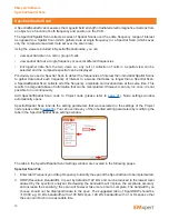
Page 41: ...y sensor that the user wishes to use and that can be connected to a supported spectrum analyzer You can carefully synchronize the positioning of the probe with the manual triggering and create high resolution spatial plots of the DUT There are four methods to further analyze the scanned data Spectral Overlay is a qualitative comparison of two frequency spectra It superimposes one frequency spectru...

Page 42: ...h a 100 MHz span 100 kHz bandwidth with a 1 GHz span so that the scan can finish in a reasonable time 3 ERX Control Level is not functional for spectral scan but is functional for a Spectral Spatial scan order to select the resolution of the spatial scan 4 Sweeps Per Cell A spectral scan operates by successively sampling the output from each selected cell in the scanner If an intermittent signal i...

Page 43: ... the scan time In the case of Spectral Scans ensure to at least have 20 to 30 of the probes selected Overlay Editor Please refer to page 34 Signal Conditioning Tab Internal Pre Amp A pre amp external to the built in spectrum analyzer but internal to the ERX l EHX is OFF by default Gain goes from 40 dB at 150 kHz to 15 dB at 8 GHz Displayed amplitude levels are automatically corrected for the gain ...

Page 44: ...gnal from the scanner bypasses the built in pre amp and attenuator section and goes to the RF OUT port to which you can connect external devices such as amplifier attenuator passband filter etc You then connect the output of such external device into the RF IN port of the built in spectrum analyzer as long as the power into the RF In port does not exceed 10 dBm To correct the displayed amplitude l...

Page 45: ...age 42 the EMxpert software replaces the previous scan data and keeps the last scan data You will only see the last scan data and display the spectral graph of this data In order to keep all scan data when running the scan continuously uncheck Replace Data When Running Continuously in the Spectral Scan settings page 42 You can display spectral graphs of all the scan data Simply click on the scan a...

Page 46: ...vered in the following pages Spatial Scan Tab 1 Enter Center Frequency manually 2 RBW Resolution Bandwidth It is set by default at 122 kHz and can be reduced to the lowest level allowed by the spectrum analyzer Decreasing the bandwidth will increase the sensitivity the scan will however take more time to complete Interleaved Scan This scan is meant to overcome the limitations of the probe polariza...

Page 47: ... last scan data In order to keep all scan data uncheck this option 9 Click Apply Spatial Scan Probes Tab Select and activate all of the probes under the DUT You can activate the probes by either left click on individual cells or left click and drag the mouse and choose Select Cells or click Select All to activate all of the probes Green indicates the activated probes You can deactivate the probes ...

Page 48: ...anner bypasses the built in pre amp and attenuator section and goes to the RF OUT port to which you can connect external devices such as amplifier attenuator passband filter etc You then connect the output of such external device into the RF IN port of the built in spectrum analyzer as long as the power into the RF In port does not exceed 10 dBm To correct the displayed amplitude levels for the ga...

Page 49: ...one scan before you run any successive scans If Replace Data When Running Continuously in the Spatial Scan settings is selected page 46 the EMxpert software replaces the previous scan data and keeps the last scan data You will only see the last scan data and display the spectral graph of this data In order to keep all scan data uncheck Replace Data When Running Continuously in the Spatial Scan set...

Page 50: ...same time This results in a large data base of information that can be manipulated It however can only run once it is not possible to run continuously Add Spectral Spatial Scan node to Project node please refer to page 31 Node settings window automatically opens Spectral Spatial Scan inherits the setting parameters that were selected in the settings of the Project node please refer to page 33 You ...

Page 51: ...feature is currently not implemented 7 Peak Hold This feature is not active for Spectral Spatial Scan 8 Click Apply Spectral Spatial Scan Probes Tab Select and activate the probes under the DUT You can activate the probes by either a left click on individual cells or by left clicking and dragging the mouse and choosing Select Cells or clicking on Select All to activate all of the probes Green indi...

Page 52: ... dBuV 150 kHz 50 MHz 50 MHz 1 GHz 1 GHz 8 GHz 56 dBm 48 dBm 39 dBm In fact when you turn ON the Internal Pre Amp you will see the following message pop up click OK if you wish to proceed External RF Bypass When ON the RF signal from the scanner bypasses the built in pre amp and attenuator section and goes to the RF OUT port to which you can connect external devices such as amplifier attenuator pas...

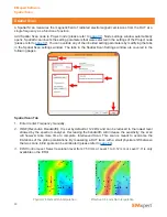
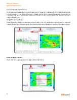
Page 53: ...ingle or multiple frequencies on the Composite Spectral view to analyze the location of them on the board Select Full Composite View under spectral graph and User Composite View under spatial view Single Frequency Marker Single Frequency Marker is selected by default Click on the frequency of interest on spectral graph A red cross will indicate the selection Spatial graph will update to display th...

Page 54: ...play the emissions on the board at the selected frequencies Selected frequencies will be displayed under Freq List Frequency List next to the spatial graph The amplitude and frequency displayed for each cell will be the maximum amplitude for that cell across the selected frequencies To clear frequency markers right click on the spectral graph and select Clear Selected Frequency Marker EMxpert Soft...

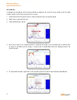
Page 55: ...w on spectral graph 2 Right click on the spectral view 3 Select Delta Marker Select 4 Move the mouse to the desired position to measure the delta In the example below delta marker is set at 11 100 MHz and the mouse is moved over to 33 200 MHz Both are displayed above the spectral graph 5 To clear delta markers right click on the spectral graph and select Clear Selected Delta Marker EMxpert Softwar...

Page 56: ...uencies Select Full Composite View under spatial graph and User Composite View under spectral view Single Frequency Marker Single Frequency Marker is selected by default Click on the cell of interest on spatial graph A cross will indicate the selection Spectral graph of the selected cell will be displayed in green on the spectral graph Multi Frequency Marker Right click on the spatial graph and se...

Page 57: ...er selected cells on to the full spectral graph Spectral graph of the selected cell will be displayed in green on the spectral graph User Composite View tab displays the spectral graph of user selected cells To clear frequency markers right click on the spatial graph and select Clear Selected Frequency Marker EMxpert Software Spectral Spatial Scan ...

Page 58: ...implemented 2 RBW Resolution Bandwidth It is set by default at 122 kHz and can be reduced to the lowest level allowed by the spectrum analyzer Decreasing the bandwidth will improve the amplitude accuracy and increase the sensitivity the scan will however take more time to complete The bandwidth you choose should not be disproportionate to the span The suggested ratio of Span RBW should be 10 000 e...

Page 59: ...tivate all of the probes Green indicates the activated probes You can deactivate the probes either left click on already selected cells or left click and drag the mouse and choose Unselect Cells or click Select None to deactivate all of the probes Using the wheel of the mouse will adjust the transparency of the JPG file to help set the probes Overlay Editor Please refer to page 34 EMxpert Software...

Page 60: ...few peaks remaining Level 2 is not working properly in this release Do not use When set to OFF the user sees the raw data as captured by the spectrum analyzer in 40 MHz IBW blocks following the reference levels of the analyzer as it goes up and down across the frequency span Noise Threshold Once at Noise Reduction Level 3 you can further decimate the data points by increasing the noise threshold f...

Page 61: ...ve the handheld probe to position B1 Click and then click OK or space bar Repeat these steps until the first row is done Return the handheld probe to A2 and then click OK or space bar Repeat these steps until all the cells are done Review that data The spatial measurements of the handheld probe are arranged as selected in the Spatial Scan area At this point the results can be treated exactly like ...

Page 62: ...ng frequency range eventhough they may have different frequency ranges e g Spectral 1 10 MHz 80 MHz and Spectral 2 30 MHz 120 MHz Add Spectral Overlay node to Project node please refer to page 31 Node settings window automatically opens After you click OK Spectral Overlay window opens Go to the Spectral View Select the data from the datalist that you want to overlay and click drag drop it on to Te...

Page 63: ...device This is especially important for conformance testing where a prototype has received EMC approval and you want to compare production units to it You would link the prototype spectrum to the reference node and compare the spectra from various production units against it by linking them to the test node Add Spectral Comparison node to Project node please refer to page 31 Node settings window a...

Page 64: ...eep this approach for the EHX Thus you will need two sections This setup is to provide a cumulative sensitivity as shown in the figure below This is a small 5x5 array taken from the larger 29x42 scanner The effect of this different sensitivity on scan results sometimes shows up when a device is rotated If the device has only H field components the scan results will be as shown in the top right of ...

Page 65: ...d scan The image on the right shows the same trace after two interleaved scans EMxpert ERX 1 Interleaved Scan a Right click on the project node and select Add Node and then Spatial Scan node and check Interleaved Scan box b Place the DUT on the scanner at the desired position This position should align with the Gerber file overlay Run the scan EMxpert Software Interleaved Scan ...

Page 66: ...Interleaved Scan a Right click on the project node and select Add Node and then Spatial Scan node and check Interleaved Scan box The scanner will automatically move up by exactly 1 row EMxpert Software Interleaved Scan ...

Page 67: ... After the first scan a message box will pop up indicating to move the DUT up by exactly 1 row Another way to describe the direction up is along the shorter axis towards the lower row numbers Do not change the orientation or position along the longer axis of the board After you move the DUT click OK to run the second scan EMxpert Software Interleaved Scan Move the DUT up by exactly 1 row ...

Page 68: ...frequency that is significantly different between the two PCBs This is useful for repairing faulty boards or pinpointing manufacturing process problems Two Spatial Scans that will compared must have overlapping cells Add Spatial Comparison node to Project node please refer to page 31 Node settings window automatically opens After you click OK Compare Spatial window opens Select the data from the d...

Page 69: ...tion and with identical scanning parameters To determine the significant emission areas on the DUT at the frequencies of interest 4 Run Spatial Scans at the relevant frequencies found in Step 3 If the peaks have not been measured accurately 5 Run narrow Spectral Scans so that the frequency error of the spectrum analyzer is less than the bandwidth used for the Spatial Scan e g for a spectrum analyz...

Page 70: ...for your DUT and use the Description portion of the setup to quickly and easily identify the purpose of the scan d Use the note facility for descriptions and possible explanations for emissions on the DUT This could come in very handy later when writing a follow up report e If you already have visited a compliance facility and have a report it is a good idea to include this data in the notes and c...

Page 71: ...can receive without being damaged 6 How sensitive is EMSCAN s patented scanner 7 How can I find the frequency of an intermittent or random signal 8 I am doing Before and After testing What feature should I use 9 Can I create Limit Lines for FCC requirements 10 I want to do a Pass or Fail test What feature should I use 11 How long does a typical Spectral Scan take 12 How long does a typical Spatial...
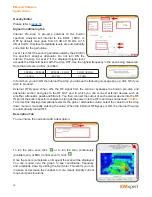
Page 72: ...er is 2 00 dB from 100 kHz to 3 GHz and 2 75 dB from 3 GHz to 8 GHz The accuracy of the probe compensation values is 3dB from 150kHz to 8GHz 4 What are the Minimum System Requirements CPU 333 MHz or faster 256 MB recommended for EHX and 8 GB recommended for ERX 8 MB Video or more Windows 7 8 8 1 OS 10 100 Network Card 5 What is the maximum power level that EMSCAN s patented scanner can receive wit...

Page 73: ...0304 that can be purchased separately Please contact EMSCAN 10 I want to do a Pass or Fail test What feature should I use Use either Spectral Overlay or Spectral Comparison feature You can also use the Threshold Red Green display with Auto scale off and set to the reference PCB emissions to see if a PCB under test is better or worse than the reference PCB To change the display color to Threshold R...

Page 74: ...ions to help design a better PCB with EMI reduction at the source Automated single probe handheld probe and EMxpert can differentiate at least between the emission from the edge where emissions from the internal layers will most likely escape and emit and from the surface of the external PCB layers If one uses a pre amplifier the scanner or probe could pick weaker signals from the internal layers ...

Page 75: ...and turning the switch to ON position you may need to replace the fuse To replace the fuse 1 Unscrew the fuse 2 Take out the burnt fuse and place the new fuse Fuse specs 3A 250V size 0 177 Dia x 0 570 L 4 50 mm x 14 48 mm 3 Screw the fuse back into the scanner EMxpert Software Appendix Fuse Replacement ...

Page 76: ...al times and turn green Please follow steps 1 to 4 in ERX EHX Quick Installation and Checklist 2 LED has turned solid green go to the control panel in Windows and access network configuration Control Panel Network and Sharing Center Change Adapter Settings Local Area Connection Select the Internet Protocol Version 4 TCP IPv4 and click on Properties Click Use the following IP address and enter the ...

Page 77: ...n file 8 Click the Upload New Image button then click OK in the message box and wait for the following screen 9 Wait for a blinking Green color LED on the unit s front panel 10 Close all the browser s open tabs and windows then reopen the web browser to the main page 11 Refresh the page as described in 2 VERY IMPORTANT 12 Repeat steps 3 and 4 but in step 4 select emsrv_m4 bin file instead EMxpert ...

Page 78: ... Window button 15 Verify the correct version by refreshing the FW upgrade page as done in steps 2 and 8 then verify the versions of both the A5 and the M4 images 16 Restart the unit by turning off the power completely then turning on You have just upgraded your ERX EHX firmware EMxpert Software Appendix How to Update Firmware ...

Page 79: ...gain later Wait for the LED to turn green The ERX is currently in the middle of setting and configuring the scan parameters Try again later Wait for the LED to turn green The ERX is currently about to perform a scan Try again later Wait for the scan to complete or press the STOP button to force a stop The ERX is currently busy general Try again later Wait for the LED to turn green The ERX is curre...

Page 80: ...equency range is outside the capabilities of the spectrum analyzer detailed range information The spectrum analyzer is not capable of running with the requested frequencies The detailed range information details what has been requested and the frequency capabilities of the attached spectrum analyzer Change the frequency limits in the settings to supported values and rerun the scan The start freque...

Page 81: ...c shock Overloaded AC outlets extension cords frayed power cords damaged or cracked wire insulation and broken plugs are dangerous They may result in a shock or fire hazard Route power supply cords so that they are not likely to be walked on or pinched by items placed upon or against them Pay particular attention to cords where they are attached to plugs and convenience receptacles and examine the...

Page 82: ...there is no guarantee that interference will not occur in a particular installation If this equipment does cause harmful interference to radio or television reception which can be determined by turning the equipment off and on the user is encouraged to try to correct the interference by one or more of the following measures Reorient or relocate the receiving antenna Increase the separation between...

Page 83: ...mark EMxpert conforms to the following standards and other related normative documents Electromagnetic emissions Council Directive 2004 108 EC EN61326 1 Ed 2 0 2012 07 CISPR 11 2009 A1 2010 FCC Part 15 B Electromagnetic immunity Council Directive 2004 108 EC EN61326 1 Ed 2 0 2012 07 IEC61000 4 2 2008 IEC61000 4 3 2006 A1 2007 A2 2010 IEC61000 4 4 2004 A1 2010 EN61000 4 5 2005 EN61000 4 6 2008 IEC6...

Page 84: ...84 Notes EMxpert Software Notes ...

Page 85: ... 1 1715 27 Avenue NE Calgary AB T2E 7E1 Canada Tel 1 403 291 0313 Fax 1 403 250 8786 www emscan com EM UM ERX EHX v 5 0 8 10 06 16 ...

Reviews: