User Manual
Section 5
GFK-2958L
May 2021
Detailed Description of I/O Modules
284
Note
: The module can be used with following Network adapters- 1. EPXPBS001 2.
EPXPNS001/EPXPNS101 3. EPXETC001 4. EPXMBE001/EPXMBE101 5. EPXEIP001
5.23.1
IO-Link overview
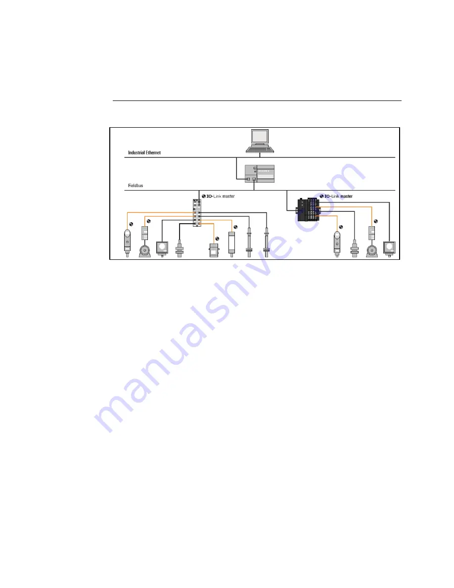
Figure 161: IO-Link for automation technology
IO-Link is a communication protocol for automation technology. IO-Link enables serial, bi-
directional point-to-point communication between devices on the sensor-actuator level
and devices on the field level or control level. Besides cyclic process data, IO-Link allows
parameters, diagnoses and identification data to be exchanged acyclically. IO-Link is
standardized worldwide in IEC 61131-
9 under the designation “single
-drop
communication interface for small sensors and actuators” (SDCI).
An IO-Link system consists of two components:
−
IO-Link Master: represents the interface between IO-Link devices and the
superordinate communication system.
−
IO-Link Device: communication-capable field device, e.g. a sensor which is
controlled by an IO-Link master.
IO-Link master and IO-Link device communicate via the switching and communication
cable C/Q. The IO-Link device is supplied with voltage by the IO-Link master via the L+ and
L- cables. Depending on the port class, an IO-Link port has additional connections:
−
Port class A: The function of the additional connections is selected by the
manufacturer. Often, this connection is occupied with an additional digital input
or output.
−
Port class B: The IO-Link master provides a second supply voltage via two further
connections.
An IO-Link device is connected with an IO-Link port of the IO-Link master with 3-cable or 5-
cable technology.


