Oxymitter 5000
1-6
Instruction Manual
IM-106-350, Rev 2.2
July 2008
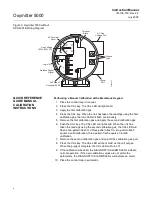
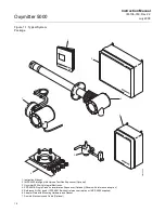
Figure 1-3. Membrane Keypad
3. Membrane keypad, Figure 1-3, and FOUNDATION fieldbus
communication are standard.
Figure 1-4. Local Operator
Interface (LOI)
4. An optional Local Operator Interface, Figure 1-4, allows continuous O
2
display and full interface capability.
5. Field replaceable cell, heater, thermocouple, and diffusion element.
6. The Oxymitter 5000 is constructed of rugged 316 L stainless steel for all
wetted parts.
DIAGNOSTIC
ALARMS
TEST
POINTS
HEATER T/C
HEATER
02 CELL
CALIBRATION
CALIBRATION RECOMMENDED
02 CELL mV +
02 CELL mv -
HEATER T/C +
HEATER T/C -
INC
INC
DEC
DEC
HIGH
GAS
LOW
GAS
CAL
TEST GAS +
PROCESS -
% 02
MEMBRANE
KEYPAD
38730056
38730057
Summary of Contents for Oxymitter 5000
Page 2: ......
Page 6: ......
Page 12: ......
Page 22: ...Oxymitter 5000 xii Instruction Manual IM 106 350 Rev 2 2 July 2008 ...
Page 42: ...Oxymitter 5000 1 20 Instruction Manual IM 106 350 Rev 2 2 July 2008 ...
Page 62: ...Oxymitter 5000 2 20 Instruction Manual IM 106 350 Rev 2 2 July 2008 ...
Page 74: ...Oxymitter 5000 4 6 Instruction Manual IM 106 350 Rev 2 2 July 2008 ...
Page 78: ...Oxymitter 5000 5 4 Instruction Manual IM 106 350 Rev 2 2 July 2008 ...
Page 94: ...Oxymitter 5000 7 6 Instruction Manual IM 106 350 Rev 2 2 July 2008 ...
Page 140: ...Oxymitter 5000 9 22 Instruction Manual IM 106 350 Rev 2 2 July 2008 ...
Page 184: ...Oxymitter 5000 B 2 Instruction Manual IM 106 350 Rev 2 2 July 2008 ...
Page 204: ...Oxymitter 5000 D 14 Instruction Manual IM 106 350 Rev 2 2 July 2008 ...
Page 222: ...Oxymitter 5000 E 18 Instruction Manual IM 106 350 Rev 2 2 July 2008 ...
Page 224: ...Instruction Manual IM 106 350 Rev 2 2 July 2008 Index 2 Oxymitter 5000 ...

