Instruction Manual
IM-106-350, Rev 2.2
July 2008
E-13
Oxymitter 5000
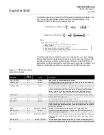
Figure E-6. PID Function Block
Diagram for Feedfoward Control
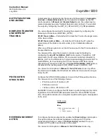
Cascade Control with
Master and Slave Loops
Situation
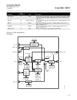
A slave loop is added to a basic PID control configuration to measure and
control steam flow to the steam heater. Variations in the steam pressure
cause the temperature in the heat exchanger to change. The temperature
variation will later be sensed by TT101. The temperature controller will modify
the valve position to compensate for the steam pressure change. The process
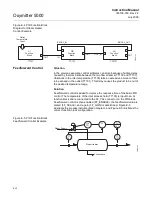
is slow and causes variations in the product temperature. Figure E-7
illustrates the process instrumentation diagram.
Figure E-7. PID Function Block
Cascade Control Example
Outlet
Temperature
Input
Inlet
Temperature
Input
BKCAL_IN
BKCAL_OUT
OUT
OUT
OUTOUT
IN
CAS_IN
FF_VAL
AI
Function
Block
AI
Function
Block
PID
Function
Block
AO
Function
Block
TT101
TC101
TCV101
TT100
38730135
38730136
Steam
Supply
FC
101
Steam Heater
Condensate
TC
101
TT
101
FT
101
TT
100
TCV
101
Summary of Contents for Oxymitter 5000
Page 2: ......
Page 6: ......
Page 12: ......
Page 22: ...Oxymitter 5000 xii Instruction Manual IM 106 350 Rev 2 2 July 2008 ...
Page 42: ...Oxymitter 5000 1 20 Instruction Manual IM 106 350 Rev 2 2 July 2008 ...
Page 62: ...Oxymitter 5000 2 20 Instruction Manual IM 106 350 Rev 2 2 July 2008 ...
Page 74: ...Oxymitter 5000 4 6 Instruction Manual IM 106 350 Rev 2 2 July 2008 ...
Page 78: ...Oxymitter 5000 5 4 Instruction Manual IM 106 350 Rev 2 2 July 2008 ...
Page 94: ...Oxymitter 5000 7 6 Instruction Manual IM 106 350 Rev 2 2 July 2008 ...
Page 140: ...Oxymitter 5000 9 22 Instruction Manual IM 106 350 Rev 2 2 July 2008 ...
Page 184: ...Oxymitter 5000 B 2 Instruction Manual IM 106 350 Rev 2 2 July 2008 ...
Page 204: ...Oxymitter 5000 D 14 Instruction Manual IM 106 350 Rev 2 2 July 2008 ...
Page 222: ...Oxymitter 5000 E 18 Instruction Manual IM 106 350 Rev 2 2 July 2008 ...
Page 224: ...Instruction Manual IM 106 350 Rev 2 2 July 2008 Index 2 Oxymitter 5000 ...


