Instruction Manual
IM-106-350, Rev 2.2
July 2008
E-7
Oxymitter 5000
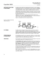
OUTPUT SELECTION
AND LIMITING
Output selection is determined by the mode and the setpoint. In Automatic,
Cascade, or RemoteCascade mode, the output is computed by the PID
control equation. In Manual and RemoteOutput mode, the output may be
entered manually (see also ”Setpoint Selection and Limiting”). You can limit
the output by configuring the OUT_HI_LIM and OUT_LO_LIM parameters.
BUMPLESS TRANSFER
AND SETPOINT
TRACKING
You can configure the method for tracking the setpoint by configuring the
following control options (CONTROL_OPTS):
SP-PV Track in Man — Permits the SP to track the PV when the target mode
of the block is Man.
SP-PV Track in LO or IMan — Permits the SP to track the PV when the
actual mode of the block is Local Override (LO) or Initialization Manual
(IMan).
When one of these options is set, the SP value is set to the PV value while in
the specified mode.
You can select the value that a master controller uses for tracking by
configuring the Use PV for BKCAL_OUT control option. The BKCAL_OUT
value tracks the PV value. BKCAL_IN on a master controller connected to
BKCAL_OUT on the PID block in an open cascade strategy forces its OUT to
match BKCAL_IN, thus tracking the PV from the slave PID block into its
cascade input connection (CAS_IN). If the Use PV for BKCAL_OUT option is
not selected, the working setpoint (SP_WRK) is used for BKCAL_OUT.
You can set control options in Manual or Out of Service mode only. When
the mode is set to Auto, the SP will remain at the last value (it will no longer
follow the PV.
PID EQUATION
STRUCTURES
Configure the STRUCTURE parameter to select the PID equation structure.
You can select one of the following choices:
• PI Action on Error, D Action on PV
• PID Action on Error
• I Action on Error, PD Action on PV
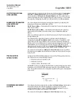
Set RESET to zero to configure the PID block to perform integral only control
regardless of the STRUCTURE parameter selection. When RESET equals
zero, the equation reduces to an integrator equation with a gain value applied
to the error:
REVERSE AND DIRECT
ACTION
To configure the block output action, enable the Direct Acting control option.
This option defines the relationship between a change in PV and the
corresponding change in output. With Direct Acting enabled (True), an
increase in PV results in an increase in the output.
You can set control options in Manual or Out of Service mode only.
38730131
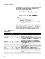
GAIN
e(s)
x
s
Where
GAIN:
proportional gain value
e:
error
s:
laplace operator
Summary of Contents for Oxymitter 5000
Page 2: ......
Page 6: ......
Page 12: ......
Page 22: ...Oxymitter 5000 xii Instruction Manual IM 106 350 Rev 2 2 July 2008 ...
Page 42: ...Oxymitter 5000 1 20 Instruction Manual IM 106 350 Rev 2 2 July 2008 ...
Page 62: ...Oxymitter 5000 2 20 Instruction Manual IM 106 350 Rev 2 2 July 2008 ...
Page 74: ...Oxymitter 5000 4 6 Instruction Manual IM 106 350 Rev 2 2 July 2008 ...
Page 78: ...Oxymitter 5000 5 4 Instruction Manual IM 106 350 Rev 2 2 July 2008 ...
Page 94: ...Oxymitter 5000 7 6 Instruction Manual IM 106 350 Rev 2 2 July 2008 ...
Page 140: ...Oxymitter 5000 9 22 Instruction Manual IM 106 350 Rev 2 2 July 2008 ...
Page 184: ...Oxymitter 5000 B 2 Instruction Manual IM 106 350 Rev 2 2 July 2008 ...
Page 204: ...Oxymitter 5000 D 14 Instruction Manual IM 106 350 Rev 2 2 July 2008 ...
Page 222: ...Oxymitter 5000 E 18 Instruction Manual IM 106 350 Rev 2 2 July 2008 ...
Page 224: ...Instruction Manual IM 106 350 Rev 2 2 July 2008 Index 2 Oxymitter 5000 ...


