
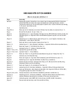

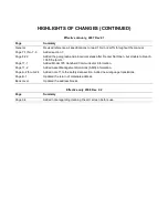


HIGHLIGHTS OF CHANGES
Effective September, 2006 Rev 2.0
Page
Summary
General
Reformatted entire manual from a two column layout. Replaced SPS 4000 information
with SPS 4001B information. Removed all references to JIS specifications. Added
information pertaining to the Local Operator Interface (LOI). Added information pertaining
to the remote electronics option.
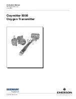
Cover
Updated photo.
Page TOC-4
Removed List of Illustrations and List of Tables from the table of contents in Rev 1.6.
Page i
Moved from backside of cover in Rev 1.4.
Page 1-2
Updated Figure 1-1, Typical System Package to show SPS 4001B and remote electronics.
Page 1-5
Updated Figure 1-2, Oxymitter 5000 AutoCalibration System Options to show the SPS
4001B.
Page 1-6
Added Figure 1-3, Membrane Keypad and Figure 1-4, Local Operator Interface (LOI).
Added step 4 under System Features.
Page 1-7
Removed step 6 under System Features from Rev 1.6.
Page 1-10
Added Figure 1-7, Typical System Installation – Oxymitter 5000 with Remote Electronics.
Page 1-11
Removed Figure 1-5, SPS 4000 from Rev 1.6.
Page 1-14
Updated Figure 1-11, Abrasive Shield Assembly.
Page 1-15 thru 1-16
Updated the specifications table.
Page 1-17 thru 1-18
Updated Table 1-1, Product Matrix.
Page 1-19
Removed Table 1-5, Single Probe Autocalibration Sequencer Coding from Rev 1.6.
Page 2-1
Added second and third Warning.
Page 2-3
Removed Figure 2-2, Oxymitter 5000 Installation (with SPS 4000) from Rev 1.6.
Page 2-4
Added Figure 2-2, Oxymitter 5000 Remote Electronics Installation.
Page 2-10
Added remote electronics information and Figure 2-8, Remote Electronics Mounting.
Page 2-11
Added both Notes and fourth Warning.
Page 2-12
Removed Figure 2-9, Terminal Block from Rev 1.6.
Page 2-13
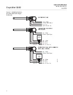
Added Figure 2-10, Electrical Installation - Oxymitter 5000 with Integral Electronics.
Page 2-14
Removed information under Electrical installation (For Oxymitter 5000 with SPS 4000),
along with Figures 2-9 and 2-10 from Rev 1.6.
Page 2-14 thru 2-15
Added information under Electrical Installation (with Remote Electronics).
Page 2-16
Added Figure 2-11, Electrical Installation - Oxymitter 5000 with Remote Electronics.
Page 2-17
Added information regarding the installation of the interconnecting cable.
page 2-19
Added body text under IMPS 4000 Connections and SPS 4001B Connections.
Page 3-1
Revised procedural steps under Terminal Block Wiring.
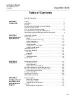
Summary of Contents for Oxymitter 5000
Page 2: ......
Page 6: ......
Page 12: ......
Page 22: ...Oxymitter 5000 xii Instruction Manual IM 106 350 Rev 2 2 July 2008 ...
Page 42: ...Oxymitter 5000 1 20 Instruction Manual IM 106 350 Rev 2 2 July 2008 ...
Page 62: ...Oxymitter 5000 2 20 Instruction Manual IM 106 350 Rev 2 2 July 2008 ...
Page 74: ...Oxymitter 5000 4 6 Instruction Manual IM 106 350 Rev 2 2 July 2008 ...
Page 78: ...Oxymitter 5000 5 4 Instruction Manual IM 106 350 Rev 2 2 July 2008 ...
Page 94: ...Oxymitter 5000 7 6 Instruction Manual IM 106 350 Rev 2 2 July 2008 ...
Page 140: ...Oxymitter 5000 9 22 Instruction Manual IM 106 350 Rev 2 2 July 2008 ...
Page 184: ...Oxymitter 5000 B 2 Instruction Manual IM 106 350 Rev 2 2 July 2008 ...
Page 204: ...Oxymitter 5000 D 14 Instruction Manual IM 106 350 Rev 2 2 July 2008 ...
Page 222: ...Oxymitter 5000 E 18 Instruction Manual IM 106 350 Rev 2 2 July 2008 ...
Page 224: ...Instruction Manual IM 106 350 Rev 2 2 July 2008 Index 2 Oxymitter 5000 ...


