background image

Oxymitter 5000

x

Instruction Manual

IM-106-350, Rev 2.2

July 2008

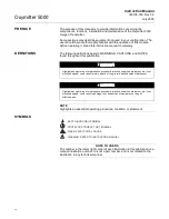
Figure 3. Oxymitter 5000 without 
SPS 4001B Wiring Diagram

QUICK REFERENCE 
GUIDE MANUAL 
CALIBRATION 
INSTRUCTIONS

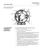
Performing a Manual Calibration with a Membrane Keypad

1. Place the control loop in manual.

2. Press the CAL key. The CAL LED will light solid.

3. Apply the first calibration gas.

4. Press the CAL key. When the unit has taken the readings using the first 

calibration gas, the CAL LED will flash continuously.

5. Remove the first calibration gas and apply the second calibration gas.

6. Push the CAL key. The CAL LED will light solid. When the unit has 

taken the readings using the second calibration gas, the CAL LED will 
flash a two-pattern flash or a three-pattern flash. A two-pattern flash 
equals a valid calibration, three-pattern flash equals an invalid 
calibration.

7. Remove the second calibration gas and cap off the calibration gas port.

8. Press the CAL key. The CAL LED will be lit solid as the unit purges. 

When the purge is complete, the CAL LED will turn off.

9. If the calibration was valid, the DIAGNOSTIC ALARMS LEDs indicate 

normal operation. If the new calibration values are not within the 
parameters, the DIAGNOSTIC ALARMS LEDs will indicate an alarm.

10. Place the control loop in automatic.

AC     L1

AC     N

+

+

-

Terminal

Block

AC Line

Voltage Port

Signal

Port

Left Side of

Oxymitter 5000

38730037

AC Terminal

Cover

Line Voltage

(85 to 264 VAC)

Ground
Lugs

Logic I/O

Fieldbus Digital

Signal

Summary of Contents for Oxymitter 5000

Page 1: ...http www raihome com Instruction Manual IM 106 350 Rev 2 2 July 2008 Oxymitter 5000 Oxygen Transmitter ...

Page 2: ......

Page 3: ...gure 1 11 Abrasive Shield Assembly Page 1 15 thru 1 16 Updated the specifications table Page 1 17 thru 1 18 Updated Table 1 1 Product Matrix Page 1 19 Removed Table 1 5 Single Probe Autocalibration Sequencer Coding from Rev 1 6 Page 2 1 Added second and third Warning Page 2 3 Removed Figure 2 2 Oxymitter 5000 Installation with SPS 4000 from Rev 1 6 Page 2 4 Added Figure 2 2 Oxymitter 5000 Remote E...

Page 4: ...moved information regarding LED Status Indicators and Table 4 1 Diagnostic Unit Alarms from Rev 1 6 Page 8 8 thru 8 21 Updated procedural steps throughout section Page 8 9 Removed Figure 4 4 Terminal Block from Rev 1 6 Updated Figure 8 3 Oxymitter 5000 with Integral Electronics Exploded View to show the LOI module and Window Cover Page 8 10 Added Figure 8 4 Oxymitter 5000 with Remote Electronics E...

Page 5: ...ph and procedural steps after Heater Not Open but Unable to Reach 736 C Setpoint Page 11 1 Added Model 375 Handheld Communicator information Page 11 2 Added Asset Management Solutions AMS information Page A 2 thru A 24 Added note 11 to the safety data section Added new language translations Page B 1 Updated the return of materials address Back cover Updated the address blocks Page Summary Page 6 4...

Page 6: ......

Page 7: ... 1 5 Handling the Oxymitter 5000 1 7 System Considerations 1 7 IMPS 4000 Optional 1 11 SPS 4001B Optional 1 11 Mounting 1 11 Operation 1 11 Probe Options 1 12 Diffusion Elements 1 12 Specifications 1 15 SECTION 2 Installation Mechanical Installation 2 2 Selecting Location 2 2 Probe Installation 2 2 Remote Electronics Installation 2 10 Electrical Installation with Integral Electronics 2 11 Electric...

Page 8: ...7 Model 375 Handheld Communicator Overview 7 1 Fieldbus Terminal Block Connections 7 1 Off Line and On Line Operations 7 2 Logic I O Configurations 7 3 Fieldbus Menu Tree 7 4 FOUNDATION Fieldbus O2 CAL Method 7 5 SECTION 8 Troubleshooting Overview 8 1 General 8 3 Alarm Indications 8 3 Alarm Contacts 8 4 Identifying and Correcting Alarm Indications 8 5 Heater Not Open but Unable to Reach 736 C Setp...

Page 9: ...Calibration Gas 11 5 Catalyst Regeneration 11 6 APPENDIX A Safety Data Safety Instructions A 2 Safety Data Sheet for Ceramic Fiber Products A 24 APPENDIX B Return of Material Returning Material B 1 APPENDIX C Fieldbus Parameter Description Fieldbus Parameters C 1 APPENDIX D Analog Input AI Function Block Simulation D 3 Filtering D 4 Signal Conversion D 5 Direct D 5 Indirect D 5 Indirect Square Roo...

Page 10: ...Transfer and Setpoint Tracking E 7 PID Equation Structures E 7 Reverse and Direct Action E 7 Reset Limiting E 8 Block Errors E 8 Modes E 8 Alarm Detection E 9 Status Handling E 10 Application Information E 10 Closed Loop Control E 10 Application Examples E 11 Basic PID Block for Steam Heater Control E 11 Feedforward Control E 12 Cascade Control with Master and Slave Loops E 13 Cascade Control with...

Page 11: ...gement representative for clarification Follow all warnings cautions and instructions marked on and supplied with the product Inform and educate your personnel in the proper installation operation and maintenance of the product Install your equipment as specified in the Installation Instructions of the appropriate Instruction Manual and per applicable local and national codes Connect all products ...

Page 12: ......

Page 13: ...roduction Preface page iv Definitions page iv Symbols page iv Oxymitter 5000 with Fieldbus Communications page v What You Need To Know page v Can You Use the Quick Start Guide page viii Quick Start Guide for Oxymitter 5000 Systems page ix Quick Reference Guide Manual Calibration Instructions page x ...

Page 14: ...lights an essential operating procedure condition or statement SYMBOLS NOTE TO USERS The number in the lower right corner of each illustration in this publication is a manual illustration number It is not a part number and is not related to the illustration in any technical manner Highlights an operation or maintenance procedure practice condition statement etc If not strictly observed could resul...

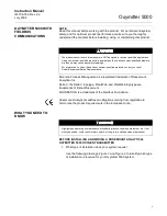
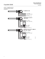
Page 15: ...quirements in the European Union WHAT YOU NEED TO KNOW BEFORE INSTALLING AND WIRING A ROSEMOUNT ANALYTICAL OXYMITTER 5000 OXYGEN TRANSMITTER 1 What type of installation does your system require Use the following drawings Figure 1 and Figure 2 to identify which type of installation is required for your Oxymitter 5000 system The products described in this manual are NOT designed for nuclear qualifie...

Page 16: ... Cal Gas 2 Cal Gas 2 OXYMITTER 5000 OXYMITTER 5000 WITH SPS 4001B OXYMITTER 5000 WITH REMOTE IMPS 4000 OPTION IMPS 4000 Line Voltage Line Voltage Line Voltage Line Voltage Line Voltage Fieldbus Digital Signal Instr Air Ref Air Cal Gas LOGIC I O LOGIC I O Instr Air Ref Air Instr Air Ref Air Ref Air Ref Air 38730054 SPS 4001B Fieldbus Digital Signal Fieldbus Digital Signal ...

Page 17: ...ine Voltage 38730102 OXYMITTER 5000 REMOTE ELECTRONICS AND IMPS WITH OXYMITTER 5000 REMOTE ELECTRONICS AND SPS 4001B WITH Cal Gas 1 Cal Gas 1 Cal Gas 2 Cal Gas 2 Line Voltage Line Voltage Instr Air Instr Air Reference Air Reference Air Calibration Gas Calibration Gas Logic I O Logic I O SPS 4001B IMPS 4000 Fieldbus Digital Signal Fieldbus Digital Signal Fieldbus Digital Signal ...

Page 18: ...e shown in Figure 1 2 Your system does NOT require an IMPS 4000 OPTION installation 3 Your system does NOT use a Remote Electronics as shown in Figure 2 4 You are familiar with the installation requirements for the Oxymitter 5000 Oxygen Transmitter You are familiar with the installation requirements for the Oxymitter 5000 Oxygen Transmitter with a SPS 4001B If you cannot use the Quick Start Guide ...

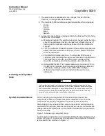
Page 19: ...Manual 5 If NOT using an SPS 4001B make the following wire connections as shown in Figure 3 line voltage fieldbus digital signal and logic I O 6 Verify the Oxymitter 5000 switch configuration is as desired Refer to Oxymitter 5000 Configuration in Section 3 Configuration of Oxymitter 5000 with Membrane Keypad or Oxymitter 5000 Configuration in Section 4 Configuration of Oxymitter 5000 with LOI 7 Ap...

Page 20: ... readings using the second calibration gas the CAL LED will flash a two pattern flash or a three pattern flash A two pattern flash equals a valid calibration three pattern flash equals an invalid calibration 7 Remove the second calibration gas and cap off the calibration gas port 8 Press the CAL key The CAL LED will be lit solid as the unit purges When the purge is complete the CAL LED will turn o...

Page 21: ...ay 7 days a week Phone 1 800 433 6076 1 440 914 1261 In addition to the CSC you may also contact Field Watch Field Watch coordinates Emerson Process Management s field service throughout the U S and abroad Phone 1 800 654 RSMT 1 800 654 7768 Emerson Process Management may also be reached via the Internet through e mail and the World Wide Web e mail GAS CSC emersonprocess com World Wide Web www rai...

Page 22: ...Oxymitter 5000 xii Instruction Manual IM 106 350 Rev 2 2 July 2008 ...

Page 23: ...ix in Table 1 1 at the end of this section to compare your order number against your unit The first part of the matrix defines the model The last part defines the various options and features of the Oxymitter 5000 Ensure the features and options specified by your order number are on or included with the unit SYSTEM OVERVIEW Scope This Instruction Manual is designed to supply details needed to inst...

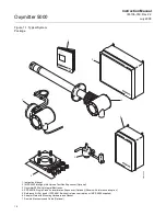
Page 24: ...1B Single Probe Autocalibration Sequencer Optional Shown with reference air option 5 Reference Air Set used if SPS 4001B without reference air option or IMPS 4000 supplied 6 Adapter Plate with Mounting Hardware and Gasket 7 Remote Electronics and Cable Optional 5 1 4 3 38730055 6 7 2 Analytical Analytical Analy tical OX YM ITTER 4000 HA ZARD OU S AR EA OX YG EN TRAN SM ITT ER Instr uctio n Man ual...

Page 25: ...nt with the distribution of some control and input output functions to field devices Speed options for process control and manufacturing applications System Description The Oxymitter 5000 is designed to measure the net concentration of oxygen in an industrial combustion processes process i e the oxygen remaining after all fuels have been oxidized The probe is permanently positioned within an exhau...

Page 26: ... probe temperature and provide an output that represents the measured oxygen concentration The power supply can accept voltages of 90 250VAC and 50 60 Hz therefore no setup procedures are required The oxygen sensing cell is maintained at a constant temperature by modulating the duty cycle of the probe heater portion of the integral electron ics The integral electronics accepts millivolt signals ge...

Page 27: ... 1 The CALIBRATION RECOMMENDED feature detects when the sensing cell is likely out of limits This may eliminate the need to calibrate on a time since last cal basis 2 The cell output voltage and sensitivity increase as the oxygen concentration decreases OXYMITTER 5000 38730092 Analytical Analytical IMPS 4000 1 to 4 Probes SPS 4001B 1 Probe ...

Page 28: ... Figure 1 4 allows continuous O2 display and full interface capability 5 Field replaceable cell heater thermocouple and diffusion element 6 The Oxymitter 5000 is constructed of rugged 316 L stainless steel for all wetted parts DIAGNOSTIC ALARMS TEST POINTS HEATER T C HEATER 02 CELL CALIBRATION CALIBRATION RECOMMENDED 02 CELL mV 02 CELL mv HEATER T C HEATER T C INC INC DEC DEC HIGH GAS LOW GAS CAL ...

Page 29: ...ations using flashing LEDs and LCD display messages Refer to the IMPS 4000 Intelligent Multiprobe Test Gas Sequencer Instruction Manual for more information Handling the Oxymitter 5000 System Considerations Prior to installing your Oxymitter 5000 make sure you have all the components necessary to make the system installation Ensure all the components are properly integrated to make the system func...

Page 30: ...ve is in addition to the stop valve in the calibration gas kit or the solenoid valves in the IMPS 4000 or SPS 4001B NOTE The electronics is rated NEMA 4X IP66 and is capable of operation at temperatures up to 185 F 85 C The optional LOI is also rated for operation at temperatures up to 185 F 85 C The infrared keypad functionality will degr ade at temperatures above 158 F 70 C Retain the packaging ...

Page 31: ... Voltage Logic I O Instrument Air Supply Reference Air Pressure Regulator Flowmeter STANDARD Oxymitter 5000 Fieldbus Digital Signal Oxymitter 5000 IMPS 4000 MULTIPROBE AUTOCALIBRATION OPTION IMPS 4000 Reference Air Logic I O Calibration Gas Adapter Plate Stack Duct Gases Calibration Gas 1 Calibration Gas 2 Inst Air Supply Line Voltage Fieldbus Digital Signal SPS 4001B SINGLE PROBE AUTOCALIBRATION ...

Page 32: ... Plate Stack Duct Gases Calibration Gas 1 Calibration Gas 2 Inst Air Supply Line Voltage Fieldbus Digital Signal Remote Electronics Remote Electronics Logic I O Line Voltage Note The IMPS 4000 or SPS 4001B must be installed in a non hazardous explosive free environment SPS 4001B SINGLE PROBE AUTOCALIBRATION OPTION WITH REFERENCE AIR OPTION Oxymitter 5000 SPS 4001B Logic I O Calibration Gas Adapter...

Page 33: ...S 4001B include a reference air flowmeter and pressure regulator The reference air flowmeter indicates the flow rate of reference air continuously flowing to the Oxymitter 5000 The reference air pressure regulator ensures the instrument air reference air flowing to the Oxymitter 5000 is at a constant pressure 20 psi 138 kPa The regulator also has a filter to remove particulates in the reference ai...

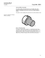
Page 34: ...sembly provides a greater filter surface area This element is also available with a flame arrestor and with a dust seal for use with an abrasive shield Figure 1 8 Ceramic Diffusion Assembly Snubber Diffusion Assembly The snubber diffusion assembly Figure 1 9 is satisfactory for most applications This element is also available with a flame arrestor and with a dust seal for use with an abrasive shie...

Page 35: ...is element is also available with a dust seal for use with an abrasive shield Figure 1 10 Hastelloy Cup Type Diffusion Assembly Abrasive Shield Assembly The abrasive shield assembly Figure 1 11 is a stainless steel tube that surrounds the probe assembly The shield protects against particle abrasion provides a guide for ease of insertion and acts as a position support especially for longer probes T...

Page 36: ...Assembly NOTE In highly abrasive applications rotate the shield 90 degrees at normal service intervals to present a new wear surface to the abrasive flow stream VIEW A VIEW B A B A B 15o 6 00 45 min 90 o 3 584 3 554 22 5o Dia on a 7 50 Dia B C ref 745 755 0 75 thru 4 pls eq sp on 4 75 B C 38730001 ...

Page 37: ...e to operate properly Probe Lengths 18 in 457 mm 12 ft 3 66 m 3 ft 0 91 m 15 ft 4 57 m 6 ft 1 83 m 18 ft 5 49 m 9 ft 2 74 m Mounting and Mounting Position Vertical or horizontal a spool piece P N 3D39761G02 is available to offset transmitter housing from hot ductwork Materials Probe Wetted or welded parts 316L stainless steel SS Non wetted parts 304 SS low copper aluminum Electronics Enclosure Low...

Page 38: ...ontact configurable as either an alarm output or as a bi directional calibration handshake signal to IMPS 4000 or SPS 4001B self powered 5 V in series with 340 ohms Conduit ports 3 4 in 14 NPT for Foundation fieldbus and logic I O signal lines Power Requirements Probe Heater 175 W nominal Electronics 10 W nominal Maximum 500 W Oxymitter Specifications ...

Page 39: ... Probe with Abrasive Shield 1 6 9 ft 2 74 m Probe 7 9 ft 2 74 m Probe with Abrasive Shield 1 8 12 ft 3 66 m Probe 9 12 ft 3 66 m Probe with Abrasive Shield 1 A 15 ft 4 57 m Probe with Abrasive Shield 1 B 18 ft 5 49 m Probe with Abrasive Shield 1 Code Mounting Hardware Stack Side 0 No Adapter Plate 1 New Installation Square Weld Plate with Studs 2 Mounting to Model 218 Mounting Plate with Model 218...

Page 40: ...erface 3 1 Membrane Keypad Fieldbus Blind Cover 2 Membrane Keypad Fieldbus Window Cover 3 Gas Fluorescent LOI Fieldbus English only Window Cover Code Language 1 English 2 German 3 French 4 Spanish 5 Italian Code Termination Filtering 00 No Option Specified as Part of Electronic Housing Code Calibration Accessories 00 No Hardware 01 Calibration Gas Flow Rotameters Reference Gas Set 02 Autocalibrati...

Page 41: ...mber Description 1A99119G01 Two disposable calibration gas bottles 0 4 and 8 O2 balance nitrogen 550 liters each 1A99119G02 Two flow regulators for calibration gas bottles 1A99119G03 Bottle rack Part Number Description Number of Oxymitters 3D39695G01 IMPS 1 3D39695G02 IMPS 2 3D39695G03 IMPS 3 3D39695G04 IMPS 4 3D39695G05 IMPS w 115 V Heater 1 3D39695G06 IMPS w 115 V Heater 2 3D39695G07 IMPS w 115 ...

Page 42: ...Oxymitter 5000 1 20 Instruction Manual IM 106 350 Rev 2 2 July 2008 ...

Page 43: ...2 19 Before installing this equipment read the Safety Instructions for the wiring and installation of this apparatus in Appendix A of this Instruction Manual Failure to follow safety instructions could result in serious injury or death Install all protective equipment covers and safety ground leads after installation Failure to install covers and ground leads could result in serious injury or deat...

Page 44: ...ore either make the necessary repairs or install the Oxymitter 5000 upstream of any leakage 3 Ensure the area is clear of internal and external obstructions that will interfere with installation and maintenance access to the membrane keypad or LOI Allow adequate clearance for removal of the Oxymitter 5000 Probe Installation 1 Ensure all components are available to install the Oxymitter 5000 If equ...

Page 45: ...VAC 48 62 Hz TM 800 433 6076 4 20 mA R 5 Amps TM HART SMART FAMILY REF GAS R H G T I N E W H C I T KE P E A I T C U EV L I M N I N L O A R P N I X E W G E S I V A T O S E H ER P 6 52 166 2 89 73 1 55 39 3 80 96 Process flow must be in this direction with respect to deflector 3534B48G01 Dia Max 2 27 58 Insulate if exposed to Ambient weather conditions Dimensions are in inches with millimeters in pa...

Page 46: ...ion 2 21 56 0 6 48 164 6 8 72 221 5 3 33 84 6 2 44 62 0 DIA 7 47 189 8 5 52 140 2 2 62 66 5 2 68 68 1 PIPE MOUNT CONFIGURATION 38730099 WALL MOUNT CONFIGURATION REMOTE ELECTRONICS WITH LOI AND WINDOW COVER REMOTE ELECTRONICS WITH MEMBRANE KEYPAD AND BLIND COVER Dimensions are in inches with millimeters in parentheses Note ...

Page 47: ...121 3 4 NPT Electrical Connection Ref Air ANSI DIN 1 4 in Tube 6 mm Tube GAS CAL Snubber Dust Seal Assembly 0 2 5 3 6 91 Dia Nominal 3 9 99 Dim A and are not pressure rated 1 These flat faced flanges are manufactured to ANSI DIN bolt patterns and Notes Removal Envelope Dim B 7 00 178 12 50 318 38730050 8 Holes Eq Sp on BC Hole Dia Flange Dia 9 00 229 9 25 235 19 0 75 24 0 94 7 50 190 7 48 190 Flan...

Page 48: ... Part numbers for adapter plates include attaching hardware Part numbers for adapter plates include attaching hardware Adapter plate for 3 6 9 and 12 ft Abrasive Shield Installations See figure 2 3 Crosshatched area in 4 corners may be used to provide additional holes for field bolting of plate to outside wall surface Adapter plate for Oxymitter 5000 Installation See Figure 2 1 4 studs lockwashers...

Page 49: ...weld pipe to adapter plate Bolt mounting plate to outside wall surface 2 50 63 5 Minimum Dia hole in wall Stack or duct metal wall Weld or bolt adapter plate to metal wall of stack or duct Joint must be air tight Field weld pipe to adapter plate 3 5 89 O D Ref Pipe 3 00 in Sched 40 Pipe Sleeve Not by length by Customer Emerson Process Management Masonry stack wall Outside wall surface Joint must b...

Page 50: ...n the hub grooves as the Oxymitter 5000 slides into the 15 forcing cone in the abrasive shield Brace Bars Not by Emerson Process Management 2 00 51 Note Dimensions are in inches with millimeters in parentheses Vertical brace clamp assy Abrasive Shield Horizontal brace clamp assy Both brace clamp assemblies are the same Installation and location of clamp assemblies and brace bars to be done in fiel...

Page 51: ...ill exceed 392 F 200 C use anti seize compound on stud threads to ease future removal of Oxymitter 5000 For ambient temperatures that will exceed 185 F 85 C we reco mmend the remote mounted electronics option 8 If insulation is being removed to access the duct work for Oxymitter 5000 mounting make sure the insulation is replaced afterward Figure 2 9 Vee Deflector Vee Deflector Diffusion Element Se...

Page 52: ...tronics unit on a stand pipe or similar structure Figure 2 2 Figure 2 8 Remote Electronics Mounting Figure 2 9 Installation with Drip Loop and Insulation Removal 38730115 P S U E I T P I C R H W E N T H G C KE N I E E R W A V I S O L P X O M T A G N I N R I T LA I V E E E H GAS CAL Drip Loop Logic I O Fieldbus Digital Signal Line Voltage Replace Insulation after Installing Oxymitter 5000 Insulatio...

Page 53: ...Logic I O Calibration Handshake Leads Use individual shielded twisted wire pairs Terminate the shield only at the electronics housing Disconnect and lock out power before connecting the power supply Install all protective covers and safety ground leads after installation Failure to install covers and ground leads could result in serious injury or death To meet the Safety Requirements of IEC 1010 E...

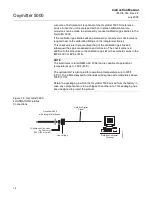
Page 54: ...ngle Probe Autocalibration Sequencer Instruction Manual c If autocalibration is not utilized a common bi directional logic contact is provided for any of the diagnostic alarms listed in Table 8 1 The assignment of alarms which can actuate this contact can be modified to one of seven additional groupings listed in Table 3 1 and Table 4 1 The logic contact is self powered 5 VDC 340 ohm series resist...

Page 55: ...RONICS WITH REMOTE SPS 4001B INTEGRAL ELECTRONICS WITH REMOTE IMPS 4000 Line 1 Neutral Ground 90 250 VAC 50 60 Hz Line Voltage Input Calibration Handshake Line Voltage Calibration Handshake Logic I O Terminal Block Ground Lugs Line 1 Neutral Ground Ground 90 250 VAC 50 60 Hz Line Voltage Input 90 250 VAC 50 60 Hz Line Voltage Input Line 1 Neutral Ground Ground Fieldbus Digital Signal Refer to SPS ...

Page 56: ...d Logic I O Calibration Handshake Leads see Figure 2 10 Use individual shielded twisted wire pairs Terminate the shield only at the electronics housing Disconnect and lock out power before connecting the power supply Install all protective covers and safety ground leads after installation Failure to install covers and ground leads could result in serious injury or death To meet the Safety Requirem...

Page 57: ...c alarms listed in Table 8 1 The assignment of alarms which can actuate this contact can be modified to one of seven additional groupings listed in Table 4 1 The logic contact is self powered 5 VDC 340 ohm series resistance An interposing relay will be required if this contact is to be utilized to annunciate a higher voltage device such as a light or horn and may also be required for certain DCS i...

Page 58: ...D BLK BLK BLU ORN YEL RED WHT BLK HTR T C O CELL 2 BY FACTORY TO ELECTRONICS FROM PROBE BLU ORN RED YEL BLK WHT PROBE REMOTE ELECTRONICS To IMPS 4000 or SPS 4001B if used Refer to IMPS 4000 or Instruction Manual SPS 4001B Logic I O Logic I O Line 1 Neutral Ground 90 250 VAC 50 60 Hz Line Voltage Input Interconnecting Cable Ground GRN GRN GRN Line Voltage Calibration Handshake Logic I O Heater Powe...

Page 59: ...tter 5000 Refer to Figure 2 12 Instrument Air Reference Air 10 psig 68 95 kPag minimum 225 psig 1551 38 kPag maximum at 1 l min 2 scfh maximum less than 40 parts per million total hydrocarbons Regulator outlet pressure should be set at 5 psi 35 kPa Reference air can be supplied by the reference air set of the IMPS 4000 or SPS 4001B If using an IMPS 4000 refer to the IMPS 4000 Intelligent Multiprob...

Page 60: ...ax 2 0 50 80 2 Mounting Holes 3 19 81 03 Lg through Body for 0 312 7 92 Dia Bolts 1 50 38 10 2 250 57 15 Schematic Hookup for Reference Air Supply on Oxymitter 5000 Probe Head Outlet 0 25 18 NPT Female Inlet Connection Instrument Air Supply 10 225 psig Max Pressure 38730033 0 250 or 6 mm O D Tubing Supplied by Customer 500 VA SERIAL NO TAG NO OXYMITTER 5000 WATTS VOLTS FUSE LINE OUTPUT Rosemount A...

Page 61: ...nd pneumatic connection NOTE Upon completing installation make sure that the Oxymitter 5000 is turned on and operating prior to firing up the combustion process Damage can result from having a cold Oxymitter 5000 exposed to the process gases During outages and if possible leave all Oxymitter 5000 units running to prevent condensation and premature aging from thermal cycling If the ducts will be wa...

Page 62: ...Oxymitter 5000 2 20 Instruction Manual IM 106 350 Rev 2 2 July 2008 ...

Page 63: ...minal Block Wiring 1 Remove cover 31 to expose terminal block 29 2 Check the terminal block wiring Figure 3 1 Be sure the power fieldbus signal and the logic outputs are properly connected and secure To avoid a shock hazard the power terminal cover must be installed For units with remote electronics check the terminal block wiring at the probe and at the remote electronics unit 3 Install housing c...

Page 64: ...ition 38730062 AC L1 AC N 500 VA SERIAL NO TAG NO OXYMITTER 5000 WATTS VOLTS FUSE LINE OUTPUT Rosemount Analytical Inc Orrville OH 44667 0901 85 264 VAC 48 62 Hz TM 800 433 6076 4 20 mA R 5 Amps TM HART SMART FAMILY DIAGNOSTIC ALARMS TEST POINTS HEATER T C HEATER 02 CELL CALIBRATION CALIBRATION RECOMMENDED 02 CELL mV 02 CELL mv HEATER T C HEATER T C INC INC DEC DEC HIGH GAS LOW GAS CAL TEST GAS PR...

Page 65: ...6 next to the membrane keypad Attach a multimeter across TP5 and TP6 The calibration and process gases can now be monitored Pressing the INC or DEC once will cause the output to switch from the process gas to the calibration gas Pressing INC or 38730063 DIAGNOSTIC ALARMS TEST POINTS HEATER T C HEATER O2 CELL CALIBRATION CALIBRATION RECOMMENDED O2 CELL mV O2 CELL mV HEATER T C HEATER T C INC INC DE...

Page 66: ...IC I O PIN MODE via FOUNDATION fieldbus or LOI The ten different modes available are explained in Table 3 1 Table 3 1 Logic I O Configuration The default condition for an Oxymitter 5000 without an IMPS 4000 or SPS 4001B The default condition for an Oxymitter 5000 with an IMPS 4000 or SPS 4001B Mode Configuration 0 The unit is not configured for any alarm condition 1 The unit is configured for a Un...

Page 67: ...mended Configuration Fieldbus Signal Upon Critical Alarm Emerson Process Management recommends that the factory default be utilized When a critical alarm occurs which causes the O2 reading to become unstable or unreliable the Oxymitter will flag the O2 reading All further O2 readings will be flagged as Out Of Service until the problem has been corrected If the O2 measurement is being utilized as p...

Page 68: ...probe provides notification to the control room that the calibration recommended diagnostic has initiated an automatic calibration through the SPS 4001B or IMPS 4000 If the O2 signal is being utilized in an automatic control loop this contact should be utilized to place the control loop into manual during calibration 3 CALIBRATION FAILED One contact per probe from an SPS 4001B or IMPS 4000 to the ...

Page 69: ...ock Wiring 1 Remove cover 31 to expose terminal block 29 2 Check the terminal block wiring Figure 4 1 Be sure the power fieldbus digital signal and logic outputs are properly connected and secure To avoid a shock hazard the power terminal cover must be installed For units with remote electronics check the terminal block wiring at the probe and at the remote electronics unit 3 Install housing cover...

Page 70: ...xymitter to be placed into simulate mode through the fieldbus interface Positions 1 3 and 4 of SW2 are not used and should remain in the OFF position 38730064 AC L1 AC N 500 VA SERIAL NO TAG NO OXYMITTER 5000 WATTS VOLTS FUSE LINE OUTPUT Rosemount Analytical Inc Solon OH 44139 85 264 VAC 48 62 Hz TM 800 433 6076 4 20 mA R 5 Amps TM HART SMART FAMILY Fieldbus Digital Signal Logic I O Ground Lugs Te...

Page 71: ...ature the O2 percentage can be read 1 To access TP5 and TP6 under the LOI module Figure 4 2 power down the Oxymitter 5000 and remove the LOI module Attach alligator leads from a multimeter across TP5 and TP6 Install the LOI module and power up the Oxymitter 5000 Allow time for the cell to reach operating temperature The calibration and process gases can now be monitored 38730065 SW2 1 2 3 4 TP1 J1...

Page 72: ...s 5 Vdc in series with a 340 ohm resistor For optimum performance Emerson Process Management recommends connecting the output to a Potter Brumfield 3 2 mA DC relay P N R10S E1Y1 J1 0K Of the ten modes in Table 4 1 mode 1 through mode 7 are the alarm modes The factory default is mode 5 for Oxymitter 5000 units without an IMPS 4000 or SPS 4001B In this mode the output will signal when a unit alarm o...

Page 73: ...tocalibration system actuated by the calibration recommended diagnostic New O2 cells may operate for more than a year but older cells may require recalibration every few weeks as they near the end of their life This strategy ensures that the O2 reading is always accurate and eliminates many unnecessary calibrations based on calendar days or weeks since previous calibration When utilizing the SPS 4...

Page 74: ...Oxymitter 5000 4 6 Instruction Manual IM 106 350 Rev 2 2 July 2008 ...

Page 75: ...is ramp cycle continues until the cell is up to operating temperature Operating Display The ramp cycle turns into a cycle where the diagnostic LEDs light in sequence from the top to the bottom one at a time After the bottom LED turns on the sequence starts again at the top with the HEATER T C LED Figure 5 1 Figure 5 1 Startup and Normal Operation DIAGNOSTIC ALARMS TEST POINTS HEATER T C HEATER O2 ...

Page 76: ...EDs will flash various blink codes Section 8 Troubleshooting In the case of multiple errors only one will be displayed based on a priority system Correct the problem and cycle power The operating display will return or the next error will be displayed The alarms are HEATER T C HEATER O2 CELL CALIBRATION CALIBRATION RECOMMENDED LED Turns on when the system determines that a calibration is recommend...

Page 77: ...he keys have been inactive for one minute the output reverts to the process gas When a calibration has been initiated the value at TP5 and TP6 is the O2 seen by the cell Oxygen levels as seen on the multimeter are 8 0 O2 8 0 volts DC 0 4 O2 0 4 volts DC CAL The CAL key can Initiate a calibration Sequence through calibration Abort the calibration NOTE Refer Section 9 Maintenance and Service for cal...

Page 78: ...Oxymitter 5000 5 4 Instruction Manual IM 106 350 Rev 2 2 July 2008 ...

Page 79: ...ur for the cell to heat to operating temperature This condition is indicated by a warm up display on the LOI Figure 6 1 This message will continue to display until the cell is up to operating temperature Operating Display The normal operating display is the O2 concentration The normal display is shown in Figure 6 2 Error If there is an error condition at startup an alarm message will be displayed ...

Page 80: ...Oxymitter 5000 6 2 Instruction Manual IM 106 350 Rev 2 2 July 2008 Figure 6 1 Startup Display Figure 6 2 O2 Concentration Display O2 Ø ØØ LK warm up 367dgC 38730088 38730089 O2 2 59 LK normal ...

Page 81: ...i sance actuation by someone brushing against the glass window raindrops dirt insects etc This lockout mode is automatically established when no but tons are pushed for 30 seconds default This countdown to lockout is con figurable In order to unlock the display input a Z pattern First push the top left gray arrow then the top right followed by the bottom left and finally the bottom right The LK no...

Page 82: ...n The new data entry value will appear in the top line of the LOI display once it is accepted The blue key bottom left acts as a selector when choosing from among a number of menu items This key will move the cursor to the right when enter ing numbers Up Down keys to the left side of the keypad are used to increment up and down when selecting from a series of menu picks They are used for increment...

Page 83: ...p IC _____mV CALIBRATION Start Calib Abort Calib Cal Constants O2 Slope ____ mV D O2 Constant ____ mV O2 Cell Imped ____ ohm Cal Status Current Calib Previous Failed Calib Pre O2 Slope _____mV D Pre O2 Constant _______mV Bad O2 Slope _____mV D Bad O2 Constant _______mV Calib Step _______ ___Sec ___H Calib Time Next O2 Cal NOTE For this menu column the selections in are user configurable All other ...

Page 84: ...o ____H ___Sec Yes No Out Tracks Next Cal Auto Calib O2 Type O2 Range O2 Alarm Leve _______ ______ l _____mA Do O2 Trim Calib Setup Input Output Parameters Status Software 38730071 CONTINUED FROM SHEET 1 Analog Digital NOTE In column four of this menu the selections in are user configurable text selections are procedures related instructions are displayed on the LOI All other parameters are displa...

Page 85: ...em is part of the system SYSTEM Input Output Analog Pertaining to the analog fieldbus digital signal representing O2 O2 Type Fieldbus digital signal may be configured to increase with increasing O2 or the reverse O2 Range Upper O2 range is user selectable O2 Alarm Level User can configure the digital output to alarm at a given O2 level Digital A bi directional logic signal may be configured as an ...

Page 86: ...and is recommended Lockout Time Keypad lockout time default is 30 sec but it is user configurable A Z keypad pattern will unlock the keypad Revert Time Once a user goes one level deep into the menu structure an additional revert time is provided to prevent nuisance lockouts One hour is the default and it is user configurable Luminance Gas fluorescence brightness is user adjustable SYSTEM Status Al...

Page 87: ...ics housing 185 F 85 C is the max Board Temp Max This is the maximum temperature that the electronics has experienced over time Voltages The raw mV signals feeding the temperature indications listed in the previous paragraph Output Values Indication of the current readings for O2 LOI INSTALLATION The LOI module connects to the top of the electronic assembly in the electronics housing There are fou...

Page 88: ...low you to monitor with a multimeter the heater thermocouple the O2 cell millivolt and the process O2 TP1 and TP2 monitor the oxygen cell millivolt output which equates to the percentage of oxygen present TP3 and TP4 monitor the heater thermocouple TP5 and TP6 monitor the process gas or the calibration gas parameter Figure 6 6 Oxymitter 5000 Test Points 38730090 TP1 J1 TP2 TP3 RED YEL GRN ORG TP4 ...

Page 89: ...ieldbus digital signal to net work the components The Handheld Communicator may be interfaced with a personal computer PC providing that special software has been installed To connect the Hand held Communicator to a PC an interface adapter is required Refer to the proper Handheld Communicator documentation in regard to the PC interface option FIELDBUS TERMINAL BLOCK CONNECTIONS Any device implemen...

Page 90: ...er to applicable Handheld documentation regarding Model 375 PC applications In the on line mode the communicator is connected to a fieldbus terminal block NOTE If the Handheld Communicator is turned on while connected to the fieldbus terminal block an undefined status indication appears while the communicator warms up Wait until the warm up period ends to continue 38730015 AC L1 AC N 4 20 Fieldbus...

Page 91: ...condition for an Oxymitter 5000 without an IMPS 4000 or SPS 4001B The default condition for an Oxymitter 5000 with an IMPS 4000 or SPS 4001B Mode Configuration 0 The unit is not configured for any alarm condition 1 The unit is configured for a Unit Alarm 2 The unit is configured for Low O2 3 The unit is configured for both a Unit Alarm and Low O2 4 The unit is configured for a High AC Impedance CA...

Page 92: ...CJ T C mV CJ Temp Value Max CJ Temp O2 Reading Value Cal slope Cal constant Cal last slope Cal last constant Cal sensor impedance Sensor impedance Sensor type Sensor SN Sensor Range EU at 100 Sensor Range EU at 0 Cal cycle state Cal state time Cal point high Cal point low Cal tracks Cal gas time Cal purge time Automatic calibration enabled Snsr Cal Date Snsr Cal Loc Name of person who calibrated t...

Page 93: ... the Oxymitter 5000 from any automatic control loops to avoid a potentially dangerous operating condition and press OK 3 From this point follow the on screen prompts to complete the calibration procedure When a step is complete select Proceed to Next Step and press the Next button 4 During the wait periods such as during a purge the Time Remaining display may be updated by selecting Update and pre...

Page 94: ...Oxymitter 5000 7 6 Instruction Manual IM 106 350 Rev 2 2 July 2008 ...

Page 95: ...ating principles When the Zirconium Oxide sensing cell is heated to its setpoint 1357 F 736 C the cell will generate a voltage that rep resents the difference between the process O2 and the reference O2 inside the probe 20 95 O2 ambient air Test points Figure 8 1 are provided to read the raw millivolt value generated by the thermocouple that controls the cell temperature and also the raw cell sign...

Page 96: ...6 C Reference Air 20 9 O2 38730096 100 10 1 0 01 0 1 0 0 50 100 150 200 Concentration O 2 EMF mV O Sensor Performance at 1357 2 O F 736O C O2 100 20 15 10 9 8 7 6 5 4 EMF mV 34 1 0 7 25 16 1 18 4 21 1 23 8 27 2 31 2 36 0 O2 3 2 1 0 8 0 6 0 5 0 4 0 2 0 1 0 01 EMF mV 42 3 51 1 66 1 71 0 77 5 81 5 86 3 101 4 116 6 166 8 ...

Page 97: ...ing installation or located where subjected to severe vibration the ICs could work loose Before troubleshoot ing the system ensure all ICs are fully seated Electrostatic Discharge Electrostatic discharge can damage the ICs used in the electronics Before removing or handling the processor board or the ICs ensure you are at ground potential ALARM INDICATIONS Once an alarm condition is identified the...

Page 98: ...er voltage device such as a light or horn An interposing relay may also be required for certain DCS input cards A Potter Brumfield R10S E1Y1 J1 0K 3 2 mA DC or an equal interposing relay will be mounted where the contact wires terminate in the control relay room If autocalibration systems are utilized the bidirectional logic contact is utilized as a hand shake signal between the autocalibration sy...

Page 99: ...0 for low calibration gas flowing One contact per IMPS 4000 for high calibration gas flowing IDENTIFYING AND CORRECTING ALARM INDICATIONS For an Oxymitter 5000 with a membrane keypad faults are indicated by four diagnostic or unit alarm LEDs A pattern of repeating blinks define the problem A condensed table of the errors and the corresponding blink codes can be found on the inside right cover of t...

Page 100: ...en High High Temp High Case Temp Low Temp High Temp 5 6 7 8 9 No No Yes Yes Yes O2 CELL 1 3 4 High mV Bad EEprom Corrupt 10 11 12 Yes Yes No CALIBRATION 1 2 3 Invalid Slope Invalid Constant Last Calibration Failed Calibration Recommended 13 14 15 Yes Yes Yes Yes Message Status Fault Number Self Clearing O2 T C OPEN Heater T C Open 1 No O2 T C SHORTED Heater T C Shorted 2 No O2 T C REVERSED Heater ...

Page 101: ... If the reading is 1 2 VDC 0 1 VDC the thermocouple is open 3 Remove power Disconnect J1 Measure the resistance across the red and yellow thermocouple leads The resistance should be approximately 1 ohm 4 If the thermocouple is open see Heater Strut Replacement in Section 9 Maintenance and Service LOI When Fault 1 is detected the LOI displays the O2 T C Open message 1 Remove power Unscrew and remov...

Page 102: ...e is likely 2 Remove power and disconnect J1 3 Measure the resistance from TP3 to TP4 The reading should be approximately 20K ohms 4 If so the short is not on the PC board The thermocouple wiring or the thermocouple is shorted See Heater Strut Replacement in Section 9 Maintenance and Service LOI When Fault 2 is detected the LOI displays the O2 T C Shorted message 1 Remove power Unscrew and remove ...

Page 103: ...P4 If the reading is negative the thermocouple wiring is reversed 2 Check red and yellow wires in the J1 connector for the proper placement 3 If the wiring is correct the fault is in the PC board See Electronic Assembly Replacement in Section 9 Maintenance and Service LOI When Fault 3 is detected the LOI displays the O2 T C Reversed message 1 Remove power Unscrew and remove the LOI module from the...

Page 104: ...repeats Figure 8 6 1 Call the factory for assistance LOI When Fault 4 is detected the LOI displays the ADC Error message 1 Call the factory for assistance 38730075 DIAGNOSTIC ALARMS TEST POINTS HEATER T C HEATER O2 CELL CALIBRATION CALIBRATION RECOMMENDED O2 CELL mV O2 CELL m HEATER T C HEATER T C V INC INC DEC DEC HIGH GAS LOW GAS CAL TEST GAS PROCESS O2 SW2 TP1 J1 TP2 TP3 RED YEL GRN ORG TP4 TP5...

Page 105: ...asure the resistance across the terminals of heater connector J8 4 The measurement should be approxi mately 72 ohms If the heater is open see Heater Strut Replacement in Section 9 Maintenance and Service LOI When Fault 5 is detected the LOI displays the O2 Heater Open message 1 Remove power Unscrew and remove the LOI module from the electronic assembly 2 Perform the diagnostic steps 2 through 4 sh...

Page 106: ...epeats replace the electronic assembly per Electronic Assembly Replacement in Section 9 Maintenance and Service LOI When Fault 6 is detected the LOI displays the Very Hi O2 Temp message 1 The very high O2 temperature alarm will activate when the thermocouple produces a voltage of 37 1 mV 1652 F 900 C 2 The triac and the temperature control may be at fault 3 Remove power Allow the Oxymitter 5000 to...

Page 107: ...xymitter 5000 is installed exceeds the ambient temperature requirements or that heat due to convection is causing case temperature to rise above the limit 3 Placing a spool piece between the stack flange and the Oxymitter 5000 flange may eliminate this problem 4 If a spool piece does not solve the problem relocation is the only solution LOI When Fault 7 is detected the LOI displays the Board Temp ...

Page 108: ...n an Open Heater fault will be displayed 3 Power down the electronics Remove the electronic assembly per Electronic Assembly Replacement in Section 9 Maintenance and Service Using a multimeter measure the resistance across the terminals of heater connector J8 4 If the heater is good the reading will be approximately 70 ohms If the heater is open see Heater Strut Replacement in Section 9 Maintenanc...

Page 109: ...ivates 2 An alarm is sent via fieldbus 3 This alarm is self clearing When temperature control is restored and the thermocouple voltage returns to the normal range the alarm clears 4 If the temperature continues to rise the next alarm will be the High High Heater Temp alarm LOI When Fault 9 is detected the LOI displays the O2 Temp Hi message Refer to the comments and procedures in paragraphs 1 thro...

Page 110: ...ecome detached from the input 2 One possible cause is connector J1 The orange or green wire has come loose from the crimped connection 3 The platinum pad could also be at fault The pad could have broken free from the back of the cell 4 Replace heater strut per Heater Strut Replacement in Section 9 Maintenance and Service If necessary replace the cell and flange assembly per Cell Replace ment in Se...

Page 111: ...vates when the cell exceeds the maximum resistance value 2 The cell should be replaced See Cell Replacement in Section 9 Maintenance and Service for cell replacement instructions LOI When Fault 11 is detected the LOI displays the O2 Cell Bad message Refer to the comments and procedures in paragraphs 1 and 2 above 38730082 LOI KEYPAD DIAGNOSTIC ALARMS TEST POINTS HEATER T C HEATER O2 CELL CALIBRATI...

Page 112: ...blem power down and then restore power The alarm should clear 3 If the alarm occurs while the unit is running there is a hardware problem on the microprocessor board 4 If cycling the power does not clear the alarm see Electronic Assembly Replacement in Section 9 Maintenance and Service LOI When Fault 12 is detected the LOI displays the EEprom Corrupt message Refer to the comments and procedures in...

Page 113: ...pad in Section 9 Maintenance and Service Verify the calibration by carefully repeating it Ensure the calibration gases match the calibration gas parameters If you attach a multimeter to TP1 and TP2 sample gas measurements are 8 O2 23 mV 0 4 O2 85 mV 3 Power down the Oxymitter 5000 and remove it from the stack 4 Replace the cell per Cell Replacement in Section 9 Maintenance and Service LOI When Fau...

Page 114: ... range 4 mV to 10 mV the alarm will activate See Calibration with Keypad in Section 9 Maintenance and Service and verify the last calibration was performed correctly 3 Power down the Oxymitter 5000 and remove it from the stack 4 Replace the cell per Cell Replacement in Section 9 Maintenance and Service LOI When Fault 14 is detected the LOI displays the O2 Cell Bad message Refer to the comments and...

Page 115: ...s when the slope and constant values calculated are out of range and the unit reverts to using the previous calibration values 2 The cell should be replaced See Cell Replacement in Section 9 Maintenance and Service for cell replacement instructions LOI When Fault 15 is detected the LOI displays the Calib Failed message Refer to the comments in paragraphs 1 and 2 above 38730086 DIAGNOSTIC ALARMS TE...

Page 116: ... calibration gas line is capped tightly between calibrations If autocal is used make sure the check valve is seating properly 2 If an abrasive shield is installed to protect the entire probe from particulate erosion a leak in the probe flange gasket can allow ambient air to migrate down the annular space between the probe and shield and then into the cell Always install a new probe flange gasket w...

Page 117: ...peed of response will degrade The O2 trend in the control room will become smoother When calibrating the calibration gas flow rate will be noted to be lower Never readjust this flow upwards Adjust this flow only when a new diffuser is installed Always note the time it takes for the cell to recover to the normal process value after the cal gas is removed As the diffuser plugs this recovery time wil...

Page 118: ...__________________________________________________________________ Date Placed Into Service __________________________________________________________________ Notes Responseinitial When the second calibration gas is turned off note the number of seconds required for the O2 value to begin migrating back to the process value Responsefinal When the second calibration gas is turned off note the number...

Page 119: ...ction 6 Startup and Operation of Oxymitter 5000 with LOI and by setting the calibration gas flowmeter The calibration gas flowmeter regulates the calibration gas flow and must be set to 5 scfh Only adjust the flowmeter to 5 scfh after placing a new diffusion element on the end of the Oxymitter 5000 Adjusting the flowmeter at any other time can pressurize the cell and bias the calibration In applic...

Page 120: ...the Oxymitter 5000 an SPS 4001B or IMPS 4000 must be installed to sequence the gases and the logic I O must be set to mode 8 via the FOUNDATION fieldbus computer terminal using the IO_PIN_MODE parameter so the sequencer and Oxymitter 5000 can commu nicate Depending on your system setup an automatic calibration can be initiated by the following methods 1 The Oxymitter 5000 s CALIBRATION RECOMMENDED...

Page 121: ...p a semi automatic calibration can be initiated by the following methods 1 Oxymitter 5000 with membrane keypad Press the CAL key on the Oxymitter 5000 keypad 2 Oxymitter 5000 with LOI Select Start Calib from the CALIBRATION menu 3 IMPS 4000 Use the IMPS 4000 keypad to change the InitCalX parameter of the CHANGE PRESETS display mode from 0000 to 0001 Refer to the IMPS 4000 Intelligent Multiprobe Te...

Page 122: ...d A timer is activated to allow the calibration gas adequate time to flow default time of five minutes When the timer times out the Oxymitter 5000 has taken the readings using the first calibration gas and the CAL LED will flash continuously The flashing indicates the Oxymitter 5000 is ready to take readings using the second calibration gas e Remove the first calibration gas and apply the second c...

Page 123: ...If the calibration was valid the DIAGNOSTIC ALARMS LEDs will indicate normal operation If either new calibration value slope or constant is not within parameters the DIAGNOSTIC ALARMS LED will indicate an alarm See Section 8 Troubleshooting for alarm codes If the calibration was invalid the Oxymitter 5000 will return to normal operation as it was before a calibration was initiated and the paramete...

Page 124: ...w Gas 1 xxxxs Read Gas 1 xxxxs Done Gas 1 The display counts down the seconds remaining to flow Gas 1 then the time remaining for sensing the O2 concentration of Gas 1 Done Gas 1 indicates completion 3 Remove the first calibration gas and apply the second calibration gas Electronics will abort the calibration if this step is not done within 30 minutes The LOI displays the following Apply Gas 2 Hit...

Page 125: ...evels of particulate the response back to the process after cal gas is also removed Previous Calibration Values from the prior good calibration Failed Calibration Bad calibration values are not loaded into the electronics Calibration Status Calibration Step The current step in an active calibration procedure Calibration Time Time until the next scheduled calibration Next O2 Cal Time until the next...

Page 126: ... and install the insulation b Connect all signal and power leads at the probe Refer to Section 2 Installation for detailed wiring instructions c Connect the calibration gas and instrument air lines to probe d Install left housing cover 31 Figure 9 3 or Figure 9 4 e Turn on instrument air f Restore power to the system refer to Power Up in Section 5 Startup and Operation of Oxymitter 5000 with Membr...

Page 127: ...Ring 11 Blind Cover 11A Window Cover Optional 12 Electronic Assembly 13 Screw 14 Membrane Keypad 14A LOI Module Optional 15 Snap Connector 16 Captive Mounting Screw 17 Microprocessor Board 18 Fuse Cap 19 Fuse 20 Power Supply Board 25 Housing 26 Screw 27 Lock Washer 28 Cable Clamp 29 Terminal Block 30 Mounting Screw 31A O Ring 32 Silicon Tube 33 Tube Clamp 34 Screw 35 Washer Note Not all parts show...

Page 128: ...or component parts of probe 1 Mounting Kit 2 Screw 3 Housing Cover 4 Wiring Diagram Label 5 Junction Box 6 Jumper Assembly Power 7 Jumper Assembly Signal 10 O Ring 11 Blind Cover 11A Window Cover Optional 12 Electronic Assembly 13 Screw 14 Membrane Keypad 14A LOI Module Optional 15 Snap Connector 16 Captive Mounting Screw 17 Microprocessor Board 18 Fuse Cap 19 Fuse 26 Screw 27 Lock Washer 28 Cable...

Page 129: ...screws 7 Figure 9 3 from the probe finned housing The probe and the electronic housing can now be separated 7 When reinstalling or replacing the electronic housing make sure that O ring 10 is in good condition Place the J1 and J8 connectors in the hole on the flat side of the electronic housing 8 Hold the J1 and J8 connectors out and to the probe side of the electronic housing Make sure that the c...

Page 130: ...Figure 9 4 on the microprocessor board top board 500 VA R SERIAL NO TAG NO OXYMITTER 4000 VOLTS WATTS OUTPUT LINE FUSE Rosemount Analytical Inc Solon OH 44139 85 264 VAC 48 62 Hz TM 800 433 6076 4 20 mA R 5 Amps TM HART SMART FAMILY 38730024 DIAGNOSTIC ALARMS TEST POINTS HEATER T C HEATER O2 CELL CALIBRATION CALIBRATION RECOMMENDED O2 CELL mV O2 CELL mv HEATER T C HEATER T C INC INC DEC DEC HIGH G...

Page 131: ...Terminal Block Replacement 1 Unscrew left housing cover 31 Figure 9 3 2 Loosen mounting screws 30 on terminal block 29 and carefully lift the block out of the housing 3 Carefully align the new terminal block on the pins so that it sits flat in the housing The round end of the terminal block should be on the opposite side of the housing conduit ports and should not be able to rotate 4 Tighten the t...

Page 132: ...lectronic assembly the rest of the way into the housing Align the electronic assembly so that it fits flush on the pins To ensure that it is flush gently try to rotate the elec tronics If the electronics rotate repeat the alignment 11 Reconnect the J1 connector to the microprocessor board Ensure the connector is secure and tighten the three captive screws on the micro processor board top board 12 ...

Page 133: ...sembly should move up 7 When the spring tension is released remove three screws 34 Grasp the wire loop and carefully slide the heater strut assembly Figure 9 8 out of the probe tube 8 When replacing the strut orient the probe so the small calibration gas tube is at the 6 o clock position of the probe tube Align the slot on the heater plate with the calibration gas line in the probe tube Slide the ...

Page 134: ...Turn the conduit ports of the housing to the CAL and REF gas ports side of the probe and position the housing on the probe d Install and tighten four screws 2 Figure 9 4 e Reconnect the probe signal cables to the probe signal and heater wire connectors Figure 9 9 Make sure the connectors are secure f Install and tighten cover 14 Follow the instructions in Removal and Replacement of Probe to instal...

Page 135: ... 9 3 or Figure 9 4 to view the component parts of the Oxymitter 5000 The cell replacement kit Figure 9 10 contains a cell and flange assembly corrugated seal setscrews socket head cap screws and anti seize compound The items are carefully packaged to preserve precise surface finishes Do not remove items from the packaging until they are ready to be used Spanner wrenches and hex wrenches needed for...

Page 136: ...ews Teflon Tubing Socket Head Cap Screws Cell and Flange Assembly Calibration Gas Passage ANSI Gasket Probe Tube Not Included in Kit Corrugated Seal Use heat resistant gloves and clothing when removing the probe Do not attempt to work on these components until they have cooled to room temperature Probe components can be as hot as 572 F 300 C This can cause severe burn s Disconnect and lock out pow...

Page 137: ...acement kit 8 Remove and discard the corrugated seal Clean the mating faces of the probe tube and retainer Remove burrs and raised surfaces with a block of wood and crocus cloth Clean the threads on the retainer and hub 9 Rub a small amount of anti seize compound on both sides of the new corrugated seal 10 Assemble the cell and flange assembly corrugated seal and probe tube Make sure the calibrati...

Page 138: ...calibration Compare probe response with previous response A broken diffusion element will cause a slower response to calibration gas Hex wrenches needed to remove setscrews and socket head screws in the following procedure are available as part of a Probe Disassembly Kit Table 10 1 Replacement Procedure 1 Follow the instructions in Removal and Replacement of Probe to remove the Oxymitter 5000 from...

Page 139: ...the right termination housing cover should not need to be removed This side of the housing contains the probe signal wire connector and the probe heater wire connector that plug into the adapter board If these wires should become disconnected or need to be replaced use the diagram in Figure 9 12 to reconnect the wires 38730052 J4 J7 J2 J5 J6 J3 Probe Signal Wire Connector Probe Heater Wire Connect...

Page 140: ...Oxymitter 5000 9 22 Instruction Manual IM 106 350 Rev 2 2 July 2008 ...

Page 141: ...8 9 32 thru 35 3D39648G11 3D39649G11 18 DIN Probe with Ceramic Diffuser 8 3 1 thru 6 8 9 32 thru 35 3D39648G12 3D39649G12 3 DIN Probe with Ceramic Diffuser 8 3 1 thru 6 8 9 32 thru 35 3D39648G13 3D39649G13 6 DIN Probe with Ceramic Diffuser 8 3 1 thru 6 8 9 32 thru 35 3D39648G14 3D39649G14 9 DIN Probe with Ceramic Diffuser 8 3 1 thru 6 8 9 32 thru 35 3D39648G15 3D39649G15 12 DIN Probe with Ceramic ...

Page 142: ...3 1 thru 6 8 9 32 thru 35 3D39649G49 15 ANSI Probe with Snubber Diffuser 8 3 1 thru 6 8 9 32 thru 35 3D39649G50 18 ANSI Probe with Snubber Diffuser 8 3 1 thru 6 8 9 32 thru 35 3D39648G43 3D39649G43 18 DIN Probe with Snubber Diffuser 8 3 1 thru 6 8 9 32 thru 35 3D39648G44 3D39649G44 3 DIN Probe with Snubber Diffuser 8 3 1 thru 6 8 9 32 thru 35 3D39648G45 3D39649G45 6 DIN Probe with Snubber Diffuser...

Page 143: ... in Kit Corrugated Seal Figure and Index Number Part Number Description 9 1 4847B61G02 ANSI 18 Cell Replacement Kit 9 1 4847B61G03 ANSI 3 Cell Replacement Kit 9 1 4847B61G04 ANSI 6 Cell Replacement Kit 9 1 4847B61G05 ANSI 9 Cell Replacement Kit 9 1 4847B61G06 ANSI 12 Cell Replacement Kit 9 1 4847B61G34 ANSI 15 Cell Replacement Kit 9 1 4847B61G35 ANSI 18 Cell Replacement Kit 9 1 4847B61G14 DIN 18 C...

Page 144: ... Kit High Sulfur HCl Resistant 9 1 4849B94G15 DIN 3 Cell Replacement Kit High Sulfur HCl Resistant 9 1 4849B94G16 DIN 6 Cell Replacement Kit High Sulfur HCl Resistant 9 1 4849B94G17 DIN 9 Cell Replacement Kit High Sulfur HCl Resistant 9 1 4849B94G18 DIN 12 Cell Replacement Kit High Sulfur HCl Resistant 2 4 3D39003G11 DIN 9 Abrasive Shield Assy 2 4 3D39003G12 DIN 12 Abrasive Shield Assy 2 4 3D39003...

Page 145: ...2 4843B37G01 Snubber Diffuser 1 12 4843B38G02 Snubber Diffuser with Dust Seal 1 12 4846B70G01 Flame Arrestor Snubber Diffuser 1 12 4846B71G01 Flame Arrestor Snubber Diffuser with Dust Seal 8 11 3534B48G01 Vee Deflector Assy 1 13 4851B89G04 Cup Type Diffusion Assembly 10 microns 1 13 4851B89G05 Cup Type Diffusion Assembly 40 microns 1 13 4851B90G04 Cup Type Diffusion Assembly Dust Seal 10 microns 1...

Page 146: ...8 4 8 6A00143G01 Adapter Board 8 4 10 120039076 O Ring 8 4 11 5R10145G01 Cover 8 4 11A 6A00170G01 Cover with Window 8 4 12 3D39862G01 Electronic Assembly 8 4 14A 6A00115G01 LOI Module Local Operator Interface 8 4 25 5R10146G01 Housing 8 4 29 08732 0002 0002 Terminal Block Transient Protected Remote Electronics 8 4 31A 120039078 O Ring 8 4 32 6A00201G01 Interconnecting Cable Assembly 20 ft 6 m 8 4 ...

Page 147: ...ckage The Model 375 Handheld Communicator is an interface device that provides a common communication link to compatible instruments such as the Oxymitter 5000 Model 375 Handheld Communications Protocol permits all the information available from the Oxymitter 5000 s electronics to be transmitted over the FOUNDATION fieldbus digital signal By attaching the handheld communicator and Oxymitter 5000 t...

Page 148: ...re 11 2 By Pass Mounting The specially designed Rosemount Analytical By Pass Package for oxygen analyzers has proven to withstand the high temperatures in process heaters while providing the same advantages offered by the in situ sensor Inconel or Kanthal steel tubes provide effective resistance to corrosion and the package uses no moving parts air pumps or other components common to other samplin...

Page 149: ... automatic calibration routines This sequencer works in conjunction with the Oxymitter 5000 CALIBRATION RECOMMENDED feature eliminating out of calibration occurrences and the need to send a technician to the installation site In addition the SPS 4001B provides a remote contact input to initiate a calibration from a remote location and relay outputs to alert when a calibration is in progress an Oxy...

Page 150: ...l mounting This cabinet provides added protection against dust and minor impacts The SPS 4001B works in conjunction with the Oxymitter 5000 s CALIBRATION RECOMMENDED feature eliminating out of calibration occurrences and the need to send a technician to the installation site In addition the SPS 4001B provides a remote contact input to initiate a calibration from a remote location and relay outputs...

Page 151: ...libration Gas and Service Kits have been carefully designed to provide a more convenient and fully portable means of testing calibrating and servicing Rosemount Analytical s oxygen analyzers These lightweight disposable gas cylinders eliminate the need to rent gas bottles For more information call Emerson Process Management at 1 800 433 6076 38730026 ...

Page 152: ...sists plugging due to catalyst fines Class I Div I Group B C and D Optional pressure balancing arrangement Optional isolation valving system permits installation and withdrawal while the process is running Specified by UOP See Application Data Sheet ADS 106 300F A01 Isolation Valving System 38730095 Oxymitter 5000 Probe in Retracted Position Isolation Valving System Integral Pressure Balancing Ass...

Page 153: ...Instruction Manual IM 106 350 Rev 2 2 July 2008 Oxymitter 5000 http www raihome com Appendix A Safety Data Safety Instructions page A 2 Safety Data Sheet for Ceramic Fiber Products page A 24 ...

Page 154: ... a mechanically operated isolating switch If not then another means of disconnecting the equipment from the supply must be provided and clearly marked as such Circuit breakers or switches must comply with a recognized standard such as IEC947 All wiring must conform with any local standards 7 Where equipment or covers are marked with the symbol to the right hazardous voltages are likely to be prese...

Page 155: ...tory Jistič může také obsahovat mechanický odpojovač Pokud ho neobsahuje musí být zajištěn a jasně označen jiný způsob odpojení zařízení od zdroje Jističe nebo přepínače musí odpovídat uznávaným normám např IEC947 Všechna zapojení musí odpovídat místním normám 7 Je li zařízení nebo kryt označen symbolem na pravé straně pravděpodobně se uvnitř nachází nebezpečné napětí Tyto kryty by měly být sejmut...

Page 156: ...nt kontakt Hvis ikke skal anden form for afbryder mellem forsyning og udstyr benyttes og mærkes som sådan Afbrydere eller kontakter skal overholde en kendt standard som IEC947 7 Hvor udstyr eller dæksler er mærket med dette symbol er farlige spændinger normalt forekom mende bagved Disse dæksler bør kun afmonteres når forsyningsspændingen er frakoblet og da kun af instrueret servicepersonale 8 Hvor...

Page 157: ...ische schakelaar bevatten Zoniet moet een andere mogelijkheid bestaan om de voedingsspanning van het toestel te halen en ook duidelijk zo zijn aangegeven Stroomonderbrekers of schakelaars moeten onderworpen zijn aan een erkende standaard zoals IEC947 7 Waar toestellen of deksels aangegeven staan met het symbool is er meestal hoogspanning aanwezig Deze deksels mogen enkel verwijderd worden nadat de...

Page 158: ...nde schakelaar Bij het ontbreken van deze voorziening dient een andere als zodanig duidelijk aangegeven mogelijkheid aanwezig te zijn om de spanning van de apparatuur af te schakelen Zekeringen en schakelaars dienen te voldoen aan een erkende standaard zoals IEC 947 7 Waar de apparatuur of de beschermdeksels kappen gemarkeerd zijn met het volgende symbool kunnen zich hieronder spanning voerende de...

Page 159: ...ur Unterbrechung der Spannungszufuhr gewährleistet werden mit Hinweisen deutlich gekennzeichnet werden Ein solcher Mechanismus zur Spannungsunterbrechung muß mit den Normen und Richtlinien für die allgemeine Installation von Elektrogeräten wie zum Beispiel der IEC947 übereinstimmen 7 Mit dem Symbol sind Geräte oder Abdeckungen gekennzeichnet die eine gefährliche Netzspannung Spannung führen Die Ab...

Page 160: ...λαµβάνει µηχανικό διακόπτη αποµόνωσης Εάν δεν περιλαµβάνει τότε άλλα µέσα αποσύνδεσης της συσκευής από την τροφοδοσία πρέπει να παροχηθούν και να σηµανθούν σαφώς ως τέτοια Οι ασφαλειοδιακόπτες ή διακόπτες πρέπει να συµµορφώνονται µε αναγνωρισµένα πρότυπα όπως το IEC947 Όλες οι καλωδιώσεις πρέπει να συµµορφώνονται µε τα τοπικά πρότυπα 7 Όπου συσκευές ή καλύµµατα είναι σηµασµένα µε το σύµβολο που ει...

Page 161: ...stasel juhul peab seadme toiteallikast lahtiühendamiseks olema teine ja selgelt osutatud moodus Automaatkorgid või lülitid peavad vastama tunnustatud standarditele nagu nt IEC947 Kogu juhtmestik peab vastama kohalikele standarditele 7 Seadmel või ümbristel asuv paremale osutav sümbol tähistab selle all leiduvat ohtlikku pinget Selliste sümbolitega ümbriseid võib eemaldada vaid juhul kui seade on t...

Page 162: ...äytyy myös sisältyä mekaaninen erotuskytkin Jos ei niin jännitesyöttö on pystyttävä katkaisemaan muilla keinoilla ja merkittävä siten että se tunnistetaan sellaiseksi Turvakytkimien tai kat kaisimien täytyy täyttää IEC947 standardin vaatimukset näkyvyydestä 7 Mikäli laite tai kosketussuoja on merkitty tällä merkillä on merkinnän takana tai alla hengenvaarallisen suuruinen jännite Suojaa ei saa poi...

Page 163: ... les conducteurs en cas d anomalie Ce disjoncteur doit également pouvoir être actionné manuellement de façon mécanique Dans le cas contraire un autre système doit être mis en place afin de pouvoir isoler l appareil et doit être signalisé comme tel Disjoncteurs et interrupteurs doivent être conformes à une norme reconnue telle IEC947 7 Lorsque les équipements ou les capots affichent le symbole suiv...

Page 164: ...nikusan mőködtethetı áramtalanító kapcsolót is Ellenkezı esetben biztosítani kell a berendezés elektromos hálózatról történı lekapcsolásának más módját és ezt világosan jelezni kell A megszakítóknak vagy kapcsolóknak meg kell felelniük egy elismert szabványnak például az IEC947 szabványnak Az összes vezetéknek meg kell felelnie az összes helyi szabványnak 7 Ha a berendezés vagy a burkolata a jobb ...

Page 165: ...ri di circuito in caso di guasto Tale interruttore dovrà inoltre prevedere un sezionatore manuale o altro dispositivo di interruzione dell alimentazione chiaramente identificabile Gli interruttori dovranno essere conformi agli standard riconosciuti quali IEC947 7 Il simbolo riportato sullo strumento o sui coperchi di protezione indica probabile presenza di elevati voltaggi Tali coperchi di protezi...

Page 166: ...s pertraukiklis taip pat gali tur ti mechaniškai veikiantį įzoliavimo jungiklį Jeigu ne tuomet turi būti nurodytos kitos įrenginio atjungimo priemon s ir aiškai pažym tos kad jos tokios yra Automatiniai perjungikliai ar jungikliai turi atitikti pripažintus standartus tokius kaip IEC947 Visi laidai turi atitikti visus vietinius standartus 7 Kur įrenginys ar dangos yra pažym ti simboliu dešin je žem...

Page 167: ...s padeves un tā atbilstoši un skaidri jāmarėē Slēdžiem jāatbilst kādam vispāratzītam standartam piemēram IEC947 Visai elektroinstalācijai jāatbilst vietējiem standartiem 7 Vietās kur iekārta vai tās pārsegi ir marėēti ar labajā pusē norādīto simbolu visticamāk zem tiem ir bīstams spriegums Šos pārsegus drīkst noĦemt tikai tad ja iekārta ir atvienota no strāvas padeves un šos darbus drīkst veikt ti...

Page 168: ...fuq il lemin x aktarx li jkun hemm vultaġġi perikolużi taħthom Dawn l għatjien għandhom jitneħħew biss meta titneħħa l provvista tad dawl mit tagħmir u minn ħaddiema tal manutenzjoni mħarrġa biss 8 Meta t tagħmir jew l għatjien ikunu mmarkati bis simbolu fuq il lemin ikun hemm periklu mill uċuħ jaħarqu li jkun hemm taħthom Dawn l għatjien għandhom jitneħħew biss minn ħaddiema tal manutenzjoni mħar...

Page 169: ...rsyningen Dersom det ikke er en mekanisk operert bryter installert må det være en annen måte å isolere utstyret fra spenningsforsyningen og denne måten må være tydelig merket Kretsbrytere eller kontakter skal oppfylle kravene i en annerkjent standard av typen IEC947 eller tilsvarende 7 Der hvor utstyr eller deksler er merket med symbol for farlig spenning er det sannsynlig at disse er tilstede bak...

Page 170: ...pięcia W przeciwnym razie naleŜy zapewnić i jasno oznaczyć inną moŜliwość odłączenia urządzenia od zasilania Wyłączniki automatyczne oraz odłączniki powinny być zgodne z uznawanymi standardami takimi jak norma IEC947 Wszystkie przewody muszą być zgodne z lokalnymi przepisami 7 Pod pokrywami lub elementami urządzenia oznaczonymi symbolem pokazanym na rysunku po prawej stronie moŜe występować niebez...

Page 171: ...oderá também conter um interruptor de isolamento accionado manualmente Caso contrário deverá ser instalado qualquer outro meio para desligar o equipamento da energia eléctrica devendo ser assinalado convenientemente Os disjuntores ou interruptores devem obedecer a uma norma reconhecida tipo IEC947 7 Sempre que o equipamento ou as tampas contiverem o símbolo é provável a existência de tensões perig...

Page 172: ... Ak nie musí byt poskytnutý iný spôsob odpojenia zariadenia od siet ového napájania a tento spôsob musí byt zreteľne označený Prerušovače obvodu alebo spínače musia byt v zhode s uznanou normou ako napr IEC947 Všetky káblové pripojenia musia vyhovovat akýmkoľvek miestnym normám 7 Tam kde je zariadenie alebo kryty označené symbolom na pravej strane sa pravdepodobne nachádza nebezpečné napätie Tieto...

Page 173: ...stikalo lahko vključuje tudi mehansko izolacijsko stikalo V nasprotnem primeru morajo biti zagotovljeni in jasno označeni drugi načini za izklop opreme iz napajanja Odklopna in druga stikala morajo biti skladna z uveljavljenimi standardi kot je IEC947 Vsa napeljava mora biti skladna z lokalnimi standardi 7 V opremi ali pod pokrovi ki so označeni s simbolom na desni je prisotna nevarna napetost Te ...

Page 174: ... fallo Los interruptores estaran de acuerdo a la norma IEC 947 u otra de reconocido prestigio 7 Cuando las tapas o el equipo lleve impreso el simbolo de tension electrica peligrosa dicho alojamiento solamente se abrira una vez que se haya interrumpido la alimentacion electrica al equipo asimismo la intervencion sera llevada a cabo por personal entrenado para estas labores 8 Cuando las tapas o el e...

Page 175: ...ljare Om så inte är fallet måste ett annat förfarande för att frånskilja utrustningen från strömförsörjning tillhandahållas och klart framgå genom markering Säkring eller omkopplare måste överensstämma med en gällande standard såsom t ex IEC947 7 Där utrustning eller hölje är markerad med vidstående symbol föreliggerisk för livsfarlig spänning i närheten Dessa höljen får endast avlägsnas när ström...

Page 176: ...ania Drive Columbia MO 65202 573 814 1300 ext 5170 573 474 9402 HEALTH HAZARD SUMMARY WARNING Possible cancer hazard based on tests with laboratory animals May be irritating to skin eyes and respiratory tract May be harmful if inhaled Cristobalite crystalline silica formed at high temperatures above 1800ºF can cause severe respiratory disease SECTION II PHYSICAL DATA APPEARANCE AND ODOR Cream to w...

Page 177: ...AZARDS SPECIAL FIRE FIGHTING PROCEDURES N A SECTION V HEALTH HAZARD DATA THRESHOLD LIMIT VALUE See Section III EFFECTS OF OVER EXPOSURE EYE Avoid contact with eyes Slightly to moderately irritating Abrasive action may cause damage to outer surface of eye INHALATION May cause respiratory tract irritation Repeated or prolonged breathing of particles of respirable size may cause inflammation of the l...

Page 178: ...ase in some measures of pulmonary function These observations are clinically insignificant In other words if these observations were made on an individual employee the results would be interpreted as being within the normal range 4 Pleural plaques thickening along the chest wall have been observed in a small number of employees who had a long duration of employment There are several occupational a...

Page 179: ...iculties administer oxygen until medical assistance can be rendered INGESTION Do not induce vomiting Get medical attention if irritation persists SKIN CONTACT Do not rub or scratch exposed skin Wash area of contact thoroughly with soap and water Using a skin cream or lotion after washing may be helpful Get medical attention if irritation persists SECTION VI REACTIVITY DATA STABILITY CONDITIONS TO ...

Page 180: ...gles to prevent eye contact Do not wear contact lenses when working with this substance Have eye baths readily available where eye contact can occur SECTION IX SPECIAL PRECAUTIONS PRECAUTIONS TO BE TAKEN IN HANDLING AND STORING General cleanliness should be followed The Toxicology data indicate that ceramic fiber should be handled with caution The handling practices described in this MSDS must be ...

Page 181: ...cess a surfactant can be used After RCF removal is completed dust suppressing cleaning methods such as wet sweeping or vacuuming should be used to clean the work area If dry vacuuming is used the vacuum must be equipped with HEPA filter Air blowing or dry sweeping should not be used Dust suppressing components can be used to clean up light dust Product packaging may contain product residue Do not ...

Page 182: ...me temperatures are prevalent 3 The valve protection cap should be left on each cylinder until it has been secured against a wall or bench or placed in a cylinder stand and is ready to be used 4 Avoid dragging rolling or sliding cylinders even for short distance they should be moved by using a suitable handtruck 5 Never tamper with safety devices in valves or cylinders 6 Do not store full and empt...

Page 183: ... equipment has been operating housing weather vibration dust etc c Site from which equipment was removed d Whether warranty or nonwarranty service is requested e Complete shipping instructions for return of equipment f Reference the return authorization number 4 Enclose a cover letter and purchase order and ship the defective equipment according to instructions provided in Emerson Process Manageme...

Page 184: ...Oxymitter 5000 B 2 Instruction Manual IM 106 350 Rev 2 2 July 2008 ...

Page 185: ...are 60 CAL_CONSTANT 20 0 mV This parameter represents the constant off set value used in the calculation of convert ing the sensor voltage to an O2 value The value of this parameter may be manually entered or calculated during a sensor cali bration 27 CAL_GAS_TIME 60 1200 Sec This is the length of time test gases are applied to the O2 probe before each measurement of the calibration cycle 22 CAL_L...

Page 186: ...to a value of 2 will cause the present calibration to be aborted 20 CAL_STATE_TIME 0 1200 Sec This is the time in seconds remaining in the present calibration state 21 CAL_TRACKS This parameter is no longer used 24 CELL_MV_VALUE INF mV This is the raw signal from the O2 sensor 43 CELL_TC_MV_VALUE 1000 0 500 0 mV This is the raw signal from the O2 sensor thermocouple 44 CELL_TEMPERATURE This is the...

Page 187: ...is is the Oxymitter s device alarm code See Table 3 52 PRIMARY_VALUE O2_VALUE 0 0 25 0 O2 This is the value that should appear on the output channel of the transducer block In the Oxymitter this is the present O2 reading and should reflect any test gas being applied 13 PRIMARY_VALUE_TYPE See section 4 1 in FF 903 0 Enumerated Selected from list in Transducer Block Specification part 2 FF 903 page ...

Page 188: ...unction Block Specification part 1 FF 890 page 49 2 TIME_TO_NEXT_CAL 0 0 9999 0 Hours This is the time remaining until the next automatic calibration 48 TRANSDUCER_ DIRECTORY See Transducer Block Specification part 1 FF 902 page 11 9 TRANSDUCER_TYPE Selected from list in Transducer Block Specification part 2 FF 903 page 39 section 4 2 10 UPDATE_EVT See Function Block Specification part 2 FF 891 pa...

Page 189: ...mocouple 3 4 MECHANICAL_FAILURE Reversed Thermocouple 4 8 N A Not a valid alarm 5 16 N A Not a valid alarm 6 32 MECHANICAL_FAILURE Heater Open Circuit 7 64 MECHANICAL_FAILURE High High Heater Temperature 8 128 MECHANICAL_FAILURE High Case Temperature 9 256 MECHANICAL_FAILURE Low Heater Temperature 10 512 MECHANICAL_FAILURE High Heater Temperature 11 1024 MECHANICAL_FAILURE Open Cell Circuit 12 204...

Page 190: ...tarted Alarm Condition Channel 1 Status Self clearing Open Thermocouple Bad No Shorted Thermocouple Bad No Reversed Thermocouple Bad No Heater Open Circuit Bad No High High Heater Temperature Bad No High Case Temperature Bad Yes Low Heater Temperature Bad Yes High Heater Temperature Bad Yes Open Cell Circuit Bad Yes High AC Impedance Cell Bad Uncertain Yes EEPROM Parameters Corrupt Bad No Calibrat...

Page 191: ...r derived values available in different channels Use the channel number to define the variable that the AI block processes The AI block supports alarming signal scaling signal filtering signal status calculation mode control and simulation In Automatic mode the block s output parameter OUT reflects the process variable PV value and status In Manual mode OUT may be set manually The Manual mode is r...

Page 192: ...to select the measurement value Refer to the appropriate device manual for information about the specific channels available in each device You must configure the CHANNEL parameter before you can configure the XD_SCALE parameter FIELD_VAL 19 Percent The value and status from the transducer block or from the simulated input when simulation is enabled GRANT_DENY 12 None Options for controlling acces...

Page 193: ...s code and number of digits to the right of the decimal point associated with OUT PV 07 EU of XD_SCALE The process variable used in block execution PV_FTIME 18 Seconds The time constant of the first order PV filter It is the time required for a 63 change in the IN value SIMULATE 09 None A group of data that contains the current transducer value and status the simulated transducer value and status ...

Page 194: ...n seconds using the PV_FTIME parameter Set the filter time constant to zero to disable the filter feature Analog Measurement Access Analog Meas CHANNEL SIMULATE OUT_SCALE XD_SCALE FIELD_VAL L_TYPE IO_OPTS PV_FTIME MODE STATUS_OPTS HI_HI_LIM HI_LIM LO_LO_LIM LO_LIM ALARM_HYS ALARM_TYPE OUT_D OUT PV Convert Cutoff Status Calc Alarm Detection NOTES OUT block output value and status OUT_D discrete out...

Page 195: ...ersion takes the square root of the value computed with the indirect signal conversion and scales it to the range and units of the PV and OUT parameters When the converted input value is below the limit specified by the LOW_CUT parameter and the Low Cutoff I O option IO_OPTS is enabled True a value of zero is used for the converted value PV This option is useful to eliminate false readings when th...

Page 196: ... AI block are defined above Process Alarm detection is based on the OUT value You can configure the alarm limits of the following standard alarms High HI_LIM High high HI_HI_LIM Low LO_LIM Low low LO_LO_LIM Condition Number Condition Name and Description 0 Other 1 Block Configuration Error the selected channel carries a measurement that is incompatible with the engineering units selected in XD_SCA...

Page 197: ...l the status handling BAD if Limited sets the OUT status quality to Bad when the value is higher or lower than the sensor limits Uncertain if Limited sets the OUT status quality to Uncertain when the value is higher or lower than the sensor limits Uncertain if in Manual mode The status of the Output is set to Uncertain when the mode is set to Manual NOTE The instrument must be in Manual or Out of ...

Page 198: ... index is calculated as a percent of OUT span and is updated at the end of the time period defined by VAR_SCAN APPLICATION INFORMATION The configuration of the AI function block and its associated output channels depends on the specific application A typical configuration for the AI block involves the following parameters Channel If the device supports more than one measurement verify that the sel...

Page 199: ...tion settings and Figure D 3 illustrates the correct function block configuration Table D 3 Analog Input Function Block Configuration for a Typical Temperature Transmitter Figure D 3 Analog Input Function Block Configuration for a Typical Temperature Transmitter Parameter Configured Values L_TYPE Direct XD_SCALE Not Used OUT_SCALE Not Used 38730122 Temperature Measurement To Another Function Block...

Page 200: ...ap Figure D 4 Figure D 4 Situation 1 Diagram Solution to Situation 1 Table D 4 lists the appropriate configuration settings and Figure D 5 illustrates the correct function block configuration Table D 4 Analog Input Function Diagram for a Pressure Transmitter used in Level Measurement Situation 1 Figure D 5 Function Block Diagram for a Pressure Transmitter used in Level Measurement 38730123 16 ft 7...

Page 201: ...he tank is empty is equivalent to 2 0 psi Figure D 6 Figure D 6 Situation 2 Diagram Solution Table D 5 lists the appropriate configuration settings Table D 5 Analog Input Function Diagram for a Pressure Transmitter used in Level Measurement Situation 2 38730125 16 ft 0 ft 2 0 psi measured at the transmitter Empty Tank Parameter Configured Values L_TYPE Indirect XD_SCALE 2 to 9 psi OUT_SCALE 0 to 1...

Page 202: ...al min and the transducer was not configured to take the square root of the differential pressure Solution Table D 6 lists the appropriate configuration settings and Figure D 7 illustrates the correct function block configuration Table D 6 Analog Input Function Block Configuration for a Differential Pressure Measurement Figure D 7 Function Block Diagram for a Differential Pressure Transmitter Used...

Page 203: ...OOS See Resource Block Diagnostics for corrective action 4 Block is not scheduled and therefore cannot execute to go to Target Mode Schedule the block to execute Process and or block alarms will not work 1 Features 2 Notification 3 Status Options 1 FEATURES_SEL does not have Alerts enabled Enable the Alerts bit 2 LIM_NOTIFY is not high enough Set equal to MAX_NOTIFY 3 STATUS_OPTS has Propagate Fau...

Page 204: ...Oxymitter 5000 D 14 Instruction Manual IM 106 350 Rev 2 2 July 2008 ...

Page 205: ...rol The block supports mode control signal scaling and limiting feedforward control override tracking alarm limit detection and signal status propagation 38730127 BKCAL_IN Theanalog input value and statusfrom another block s BKCAL_OUT output that is used for backward output tracking for bumpless transfer and to pass limit status CAS _IN setpoint The remote value from another function block FF_VAL ...

Page 206: ...n the alarm limit before the associated active alarm condition clears ALARM_SUM 45 None The summary alarm is used for all process alarms in the block The cause of the alert is entered in the subcode field The first alert to become active will set the Active status in the Status parameter As soon as the Unreported status is cleared by the alert reporting task another block alert may be reported wit...

Page 207: ... PV_SCALE The setting for the alarm limit use to detect the deviation low alarm condition DV_LO_PRI 58 None The priority of the deviation low alarm ERROR 67 EU of PV_SCALE The error SP PV used to determine the control action FF_ENABLE 70 None Enables the use of feedforward calculations FF_GAIN 42 None The feedforward gain value FF_VAL is multiplied by FF_GAIN before it is added to the calculated c...

Page 208: ...nd status that is provided by a supervisory host Used when mode is ROUT ROUT_OUT 36 EU of OUT_SCALE Block output that is provided to a supervisory host for a back calculation to allow action to be taken under limiting conditions or mode change Used when mode is RCAS SHED_OPT 34 None Defines action to be taken on remote control device time out SP 08 EU of PV_SCALE The target block setpoint value It...

Page 209: ...AMMA 71 Percent Used to set disturbance rejection vs tracking response action for a 2 0 degree of freedom PID UPDATE_EVT 43 None This alert is generated by any changes to the static data Parameter Index Number Units Description 38730129 FF_VAL BKCAL_IN TRK_IN_D CAS_IN IN TRK_VAL FF_GAIN FF_SCALE RCAS_OUT RCAS_IN SP_HI_LIM SP_LO_LIM SP_RATE_DN SP_RATE_UP SP_FTIME GAIN RATE RESET Feedforward Calcula...

Page 210: ...ime constant in seconds using the PV_FTIME or SP_FTIME parameters Set the filter time constant to zero to disable the filter feature FEEDFORWARD CALCULATION The feedforward value FF_VAL is scaled FF_SCALE to a common range for compatibility with the output scale OUT_SCALE A gain value FF_GAIN is applied to achieve the total feedforward contribution TRACKING You enable the use of output tracking th...

Page 211: ...L_OUT on the PID block in an open cascade strategy forces its OUT to match BKCAL_IN thus tracking the PV from the slave PID block into its cascade input connection CAS_IN If the Use PV for BKCAL_OUT option is not selected the working setpoint SP_WRK is used for BKCAL_OUT You can set control options in Manual or Out of Service mode only When the mode is set to Auto the SP will remain at the last va...

Page 212: ...T may be set manually Automatic Auto The SP may be set manually and the block algorithm calculates OUT Cascade Cas The SP is calculated in another block and is provided to the PID block through the CAS_IN connection RemoteCascade RCas The SP is provided by a host computer that writes to the RCAS_IN parameter RemoteOutput Rout The OUT is provided by a host computer that writes to the ROUT_IN parame...

Page 213: ...ional process alarm detection is based on the difference between SP and PV values and can be configured via the following parameters Deviation high DV_HI_LIM Deviation low DV_LO_LIM In order to avoid alarm chattering when the variable is oscillating around the alarm limit an alarm hysteresis in percent of the PV span can be set using the ALARM_HYS parameter The priority of each alarm is set in the...

Page 214: ...nds immediately and directly to a change in the PV or SP The proportional term GAIN applies a change in the loop output based on the current magnitude of the error multiplied by a gain value The integral control function reduces the process error by moving the output in the appropriate direction The integral term RESET applies a correction based on the magnitude and duration of the error Set the R...

Page 215: ...il a Good input status is reestablished APPLICATION EXAMPLES Basic PID Block for Steam Heater Control Situation A PID block is used with an AI block and an AO block to control the flow steam used to heat a process fluid in a heat exchanger Figure E 3 illustrates the process instrumentation diagram Figure E 3 PID Function Block Steam Heater Control Solution The PID loop uses TT101 as an input and p...

Page 216: ...dded to improve the response time of the basic PID control The temperature of the inlet process fluid TT100 is input to an AI function block and is connected to the FF_VAL connector on the PID block Feedforward control is then enabled FF_ENABLE the feedforward value is scaled FF_SCALE and a gain FF_GAIN is determined Figure E 5 illustrates the process instrumentation diagram and Figure E 6 illustr...

Page 217: ... will later be sensed by TT101 The temperature controller will modify the valve position to compensate for the steam pressure change The process is slow and causes variations in the product temperature Figure E 7 illustrates the process instrumentation diagram Figure E 7 PID Function Block Cascade Control Example Outlet Temperature Input Inlet Temperature Input BKCAL_IN BKCAL_OUT OUT OUT OUTOUT IN...

Page 218: ...er function blocks for complex control strategies Figure C 9 illustrates the function block diagram for cascade control with override When configured for cascade control with override if one of the PID function blocks connected to the selector inputs is deselected that PID block filters the integral value to the selected value the value at its BKCAL_IN The selected PID block behaves normally and t...

Page 219: ... the AI block in Manual mode and set the output to some nominal value for use in the Integrator function block In this case IN at the slave PID block is constant and prevents the integral term from increasing or decreasing Figure E 9 Function Block Diagram for Cascade Control with Override 38730138 PID Function Block AO Function Block PID Function Block Control Selector Function Block PID Function...

Page 220: ...o execute Mode will not leave IMAN 1 Back Calculation 1 BKCAL_IN a The link is not configured the status would show Not Connected Configure the BKCAL_IN link to the downstream block b The downstream block is sending back a Quality of Bad or a Status of Not Invited See the appropriate downstream block diagnostics for corrective action Mode will not change to AUTO 1 Target mode not set 2 Input 1 Set...

Page 221: ...utput value 2 Shed timer 1 Host system is not writing ROUT_IN with a quality and status of good cascade within shed time see 2 below 2 The mode shed timer SHED_RCAS in the resource block is set too low Increase the value Process and or block alarms will not work 1 Features 2 Notification 3 Status Options 1 FEATURES_SEL does not have Alerts enabled Enable the Alerts bit 2 LIM_NOTIFY is not high eno...

Page 222: ...Oxymitter 5000 E 18 Instruction Manual IM 106 350 Rev 2 2 July 2008 ...

Page 223: ...000 11 3 Installation Electrical 2 11 Mechanical 2 2 Pneumatic 2 17 Remote Electronics 2 10 K Kit Cell Replacement 9 18 Probe Disassembly 10 5 L Local Operator Interface 6 1 Logic I O Configurations 7 3 Logic I O Mode 4 5 LOI Menu Tree 6 4 LOI Lockout 6 3 M Maintenance 9 1 Material Safety Data Sheet A 24 Membrane Keypad 5 2 Menu Tree Fieldbus 7 4 LOI 6 4 Model 375 7 1 O O2 CAL Method Foundation Fi...

Page 224: ...Instruction Manual IM 106 350 Rev 2 2 July 2008 Index 2 Oxymitter 5000 ...

Page 225: ...es for any failure of Rosemount Analytical to comply with the warranty provisions whether claims by the purchaser are based in contract or in tort including negligence Rosemount Analytical does not warrant equipment against normal deterioration due to environment Factors such as corrosive gases and solid particulates can be detrimental and can create the need for repair or replacement as part of n...

Page 226: ...agement Asia Pacific Private Limited 1 Pandan Crescent Singapore 128461 Republic of Singapore T 65 6 777 8211 F 65 6 777 0947 E analytical ap emersonprocess com ROSEMOUNT ANALYTICAL EUROPE Emerson Process Management Gmbh co OHG Industriestrasse 1 63594 Hasselroth Germany T 49 6055 884 0 F 49 6055 884 209 WORLD HEADQUARTERS Emerson Process Management Rosemount Analytical Inc 6565P Davis Industrial ...

Reviews: