Oxymitter 5000
8-4
Instruction Manual
IM-106-350, Rev 2.2
July 2008
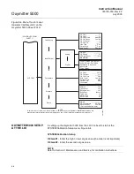
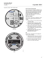
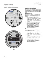
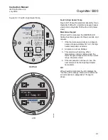
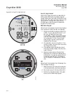
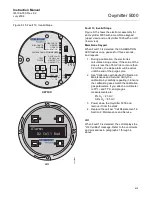
Figure 8-2. Diagnostic LEDs
ALARM CONTACTS
If autocalibration is not utilized, a common bidirectional logic contact is pro-
vided for any of the diagnostic alarms listed in Table 8-1. The assignment of
alarms which can actuate this contact can be modified to one of seven addi-
tional groupings (mode 0 through mode 7) listed in Table 3-1.
The logic contact is self-powered, +5 VDC, with a 340 ohm series resistance.
An interposing relay will be required if this contact is to be utilized to annunci-
ate a higher voltage device, such as a light or horn. An interposing relay may
also be required for certain DCS input cards.
A Potter & Brumfield R10S-E1Y1-J1.0K 3.2 mA DC or an equal interposing
relay will be mounted where the contact wires terminate in the control/relay
room.
If autocalibration systems are utilized, the bidirectional logic contact is utilized
as a "hand-shake" signal between the autocalibration system (SPS 4001B or
IMPS 4000) and is unavailable for alarming purposes. Additional contacts are
provided through the autocalibration systems, noted below.
38730097
DIAGNOSTIC
ALARMS
TEST
POINTS
HEATER T/C
HEATER
02 CELL
CALIBRATION
CALIBRATION RECOMMENDED
02 CELL mV +
02 CELL mv -
HEATER T/C +
HEATER T/C -
INC
INC
DEC
DEC
HIGH
GAS
LOW
GAS
CAL
TEST GAS +
PROCESS -
% 02
Diagnostic
LEDs
Summary of Contents for Oxymitter 5000
Page 2: ......
Page 6: ......
Page 12: ......
Page 22: ...Oxymitter 5000 xii Instruction Manual IM 106 350 Rev 2 2 July 2008 ...
Page 42: ...Oxymitter 5000 1 20 Instruction Manual IM 106 350 Rev 2 2 July 2008 ...
Page 62: ...Oxymitter 5000 2 20 Instruction Manual IM 106 350 Rev 2 2 July 2008 ...
Page 74: ...Oxymitter 5000 4 6 Instruction Manual IM 106 350 Rev 2 2 July 2008 ...
Page 78: ...Oxymitter 5000 5 4 Instruction Manual IM 106 350 Rev 2 2 July 2008 ...
Page 94: ...Oxymitter 5000 7 6 Instruction Manual IM 106 350 Rev 2 2 July 2008 ...
Page 140: ...Oxymitter 5000 9 22 Instruction Manual IM 106 350 Rev 2 2 July 2008 ...
Page 184: ...Oxymitter 5000 B 2 Instruction Manual IM 106 350 Rev 2 2 July 2008 ...
Page 204: ...Oxymitter 5000 D 14 Instruction Manual IM 106 350 Rev 2 2 July 2008 ...
Page 222: ...Oxymitter 5000 E 18 Instruction Manual IM 106 350 Rev 2 2 July 2008 ...
Page 224: ...Instruction Manual IM 106 350 Rev 2 2 July 2008 Index 2 Oxymitter 5000 ...

