


46
EATON
www.eaton.com
Instruction Booklet
IB020003EN
Effective January 2021
AMPGARD RVSS
Reduced Voltage Soft-Starter
User Manual
Section 9: Programming
9.1 Overview
This section covers the RVSS soft start configuration. For information
on how to change the Base Control Module or I/O Board firmware,
see
and
The AMPGARD RVSS will arrive at the customer’s site programmed
with the purchased softstart features, for the motor specified.
However, during initial startup activities, it may be necessary to tune
the configuration for the motor and connected load, the customer’s
desired performance, and the available AC supply system. To do
this, either the Monitoring User Interface or a PC equipped with
PowerXpert
inControl software can be used.
MUI Monitoring User Interface
•
Easy start-up wizard for configuring critical parameters. The wizard will appear on
first power-up attempt and can also be prompted in the
PRG | Services
menu.
•
PRG
menu allows you to easily view or change any system parameter. Parameters
are broken into simple menu groups so that it is easy to find what you are looking for
without requiring use of any documentation. See
for
more details on the Monitoring User Interface.
•
The MUI programming mode (
PRG
) is interactive. Choosing an Operation Mode
determines what Soft Start Configuration subsequent menu choices are offered.
Power Xpert
inControl Software configuration and monitoring tool
This Software Tool may be downloaded free of change from the
Eaton website (see
). It is a powerful Software Tool with
many features including:
•
Start-up wizard for configuring the most critical motor nameplate parameters.
•
Categorized parameters for ease of finding the parameters needed to enable and
configure particular features in the C445
•
Ability to save configuration files for easy access later or to open and download to a
replacement BCM
•
Motor Control page to monitor run status, some motor parameters such as average
current and voltage as well as fault and warning codes and descriptions.
•
Parameter compare feature between two different configuration files.
•
Online and off-line configuration for a C445 along with the ability to upload from an
on-line device to an off-line file and from an off-line file to a device.
This section will address how to configure the RVSS using either
of these two methods. Their features are summarized below, and
their details will be addressed in later sections. Parameter titles
are sometimes abbreviated on the MUI display, but the application
menus are the same for both the MUI and
inControl.
9.2 MUI operations
The RVSS can be configured and run from the Monitoring User
Interface (MUI). Mounted on the RVSS cell low voltage compartment
door, the MUI has local control buttons for Start, Stop, Auto mode,
Reset, and Mode/Back membrane switch buttons. In addition, it has
indicating LEDs for Status, Fault, Warn, Run, Stop and Auto mode
(see
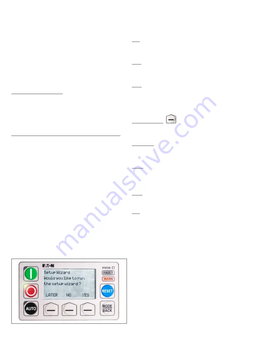
shows the MUI on power up, offering the
Setup Wizard.
Figure 45. Monitoring user interface (MUI) on power-up.
9.2.1 Control buttons
RUN
The green Run button has an LED in its upper left. The green LED
flashes when the RVSS is starting and illuminates steadily when the
RVSS is running. Press the Run button to start the RVSS. In JOG
mode, press the Run button to start a jog, and STOP to stop it.
STOP
The red Stop button has an LED in its upper left. The green LED
flashes when the RVSS is inhibited, and illuminates steadily when
the RVSS is stopped. Press the Stop button to stop the RVSS once it
is started or running.
AUTO
The black Auto button has an LED in its upper left. The green LED
illuminates steadily when control has been given to a remote source.
Press the Auto button to give control to an established remote
source.
Note: when the remote source has control, the Run and Stop
buttons are not active. Control must be returned to the MUI for the
buttons to work.
Contextual buttons
The bottom row contextual buttons function based upon the
choices offered on the LCD display above them. They may be used
for display menu navigation or, inputing selections or changing
parameter setpoints.
MODE/BACK
The Mode/Back button us used to toggle through the display top row
menus, to go back when navigating within menus, or, when pressed
and held, to go back to the main monitoring menu from multiple
layers deep.
RESET
Use the Reset button to reset system faults when indicated by the
Fault LED indicator.
9.2.2 Status display indicators
In the upper right of the MUI, there are three LED status indicators.
Status
The Status indicator shows communications activity between the
MUI and the Base Control Module (BCM). When active, it flashes
around once per second.
Fault
The Fault indicator illuminates when there is a system fault and turns
off when the fault is cleared. A fault that failed to reset will cause
the Fault indicator to flash.


