3-26 Programming
Setpoint Use
Menu Path
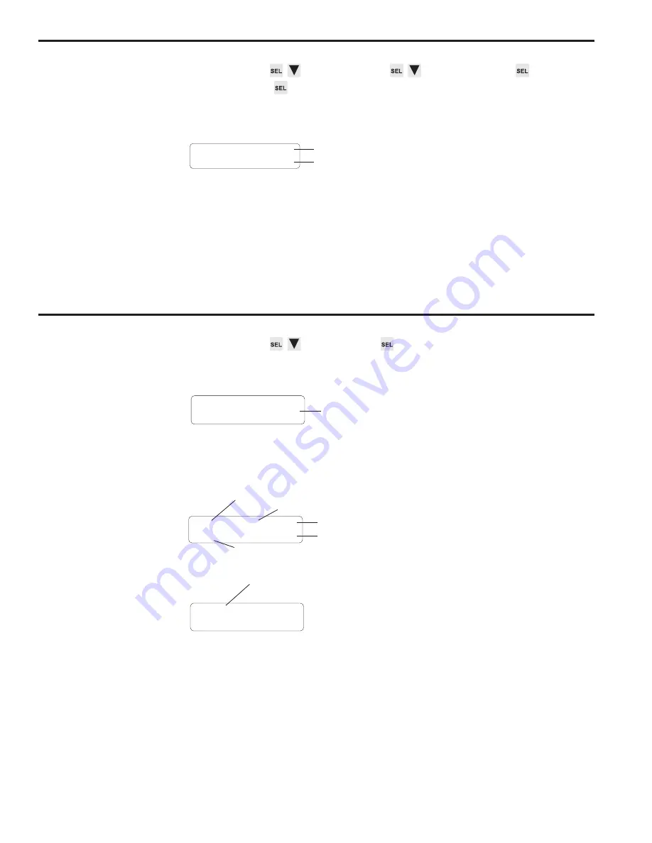
MAIN SCREEN to SETUP MENU to SYSTEM INFO
SETPOINT USE
Purpose
This function displays the total number of setpoint On/Off pairs, or “pulses” available
for programming, and the number of pulses that have been programmed.
Screen
The number of setpoints shown as “Used” is the sum of all pulses that are programmed
into all channels of all programs. The “Total” value is the number of pulses that can be
stored in non-volatile EEPROM memory. The difference between the two numbers is
the number of pulses available for programming.
The number of pulses programmed into all channels of all programs cannot exceed the
value displayed as Total.
There are no values that can be changed in this screen.
Setpoints
Menu Path
MAIN SCREEN to SETPOINTS
Screens
When SETPOINTS is selected, a preliminary screen specifies the program whose
setpoints will be programmed.
The active program is displayed, but any other program can be specified by using the
numeric keys or INC and DEC to choose a program, then pressing SEL to move to
setpoint programming.
(continued)
Channel to Edit
Use the numeric keypad and ENT to select the channel to program.
• Channels 91 through 96 are special channels used for Output Grouping and
Modes. See Section 5 for details.
Setpoint Values
Use the left and right arrow keys to move between the ON and OFF setpoints.
• If a channel has more than one pulse, you may view the other pulses by pressing
the right cursor key when viewing the OFF setpoint, or by pressing the left cursor key
when viewing the ON setpoint.
PGM NUMBER: <
Program to view or modify
CH: 1 <EDG
ON: 90 OF: 270
Pulse mode
OFF setpoint
ON setpoint
Channel
Blank if only 1 pulse in channel
<-P-> CH:1<EDG
ON: 90 OF: 270
<-P-> indicates multiple pulses in channel
TOTAL: 1200
USED: 64
Total number of pulses available for programming
Number of pulses programmed into all channels
of all programs
Summary of Contents for Plus PS-6144 Series
Page 3: ......
Page 4: ......
Page 12: ...2 2 Installation Wiring Mounting Dimensions Figure 4 Mounting Dimensions ...
Page 114: ......
Page 115: ......


