3-18 Programming
Output Enable ANDing
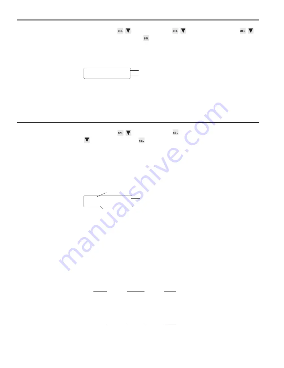
Menu Path
MAIN SCREEN to CONFIG MENU to CHN ANDING MENU to
OUTPUT ENABLE ANDING
Purpose
Output Enable ANDing allows you to AND any output channels with Input Terminal #16,
Figure 7. A channel ANDed with this terminal will be enabled to turn on at its programmed
setpoints only while the terminal is energized.
Screen
CHN: 12<
OUTPUT AND: OFF
Channel number
Output Enable ANDing: ON or OFF.
(Toggle with SEL key)
Programming
Select a new channel by pressing INC/DEC, or using the numeric keys followed by ENT.
Use the SEL key to toggle ANDing on and off.
Output Groups
M
enu Path
MAIN SCREEN to CONFIG MENU
to OUTPUT GROUPS
Purpose
This function allows you to divide output channels into groups, and assign operating
modes to the groups. Operating modes provide a powerful tool for relating output channel
operation to sensor signals or other inputs. Incorporating modes into a control system
can greatly improve line efficiency, reduce scrap, and improve control accuracy between
machine sections at high speeds. See Section 5 for a complete explanation of the uses
and applications of operating modes.
Screen
Establishing Groups
When dividing outputs into groups, keep these rules in mind:
• Output channels are assigned to groups sequentially. Group 1 will begin with Output
1 and include the specified number of outputs; Group 2 will begin with the next output
and continue sequentially for its specified number of outputs; and so on. The last
group will automatically include all of the remaining outputs.
• You can establish as many as six groups or as few as one.
• More than one group can be assigned to the same mode.
Grouping Example 1—All Outputs in One Group
Output
Includes
Group
Outputs
Mode
1
1 thru 25
3
Grouping Example 2—Two Groups
Output
Includes
Group
Outputs
Mode
1
1 thru 4
2
2
5 thru 25
0
(continued)
GRP:1 <GRP QTY:2
CHNS: 15 MODE: 3
Number of output groups
Enable mode of selected group
Number of channels in selected group
Selected group number
Summary of Contents for Plus PS-6144 Series
Page 3: ......
Page 4: ......
Page 12: ...2 2 Installation Wiring Mounting Dimensions Figure 4 Mounting Dimensions ...
Page 114: ......
Page 115: ......


