6-46
6205s2 BATHYMETRIC AND SIDE SCAN SONAR
0025262_REV_A
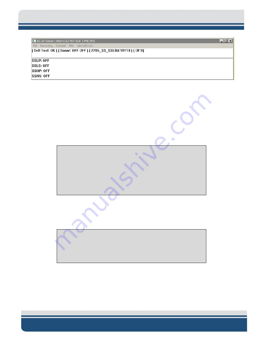
Figure 6-3: Sonar 192.9.0.101 Remote Desktop Connection Window
2.
Click on
Menu
>
Misc
>
Serial Port Information
.
3.
Check each COM port in the dropdown menu to ensure the correct baud rates are set and data is
coming through for each device and in the correct format, as shown in
a.
COM1 = MRU
b.
COM2 = GNSS
c.
COM4 = Sound Velocity Sensor located in the sonar head’s housing
NOTE:
GNSS and MRU are interchangeable on COM1 and COM2 as long
as the appropriate baud rate is set in the dropdown menu next to channel
assignment in Serial Port Information Window, as shown in
red arrow.
More information on how to configure the COM ports is presented in
CONFIGURING
COM
PORTS.
If all systems are working properly, close this window and proceed to Step 4. If there is an issue
with one of the ports, contact
CAUTION!
Sound velocity is extremely important for the system to
operate correctly. When sound velocity measurements are not present
(i.e., the port is reporting no data), use
to go through the troubleshooting process.
Summary of Contents for 6205S2
Page 32: ...2 32 Figure 2 2 6205s2 Sonar Head with Adaptor Flange ICD...
Page 33: ...2 33 Figure 2 3 6205s2 Side Scan Transducer...
Page 34: ...2 34 Figure 2 4 6205s2 Side Scan Transducer Details...
Page 35: ...2 35 Figure 2 5 6205s2 Deck Cable Wiring Diagram...
Page 36: ...2 36 Figure 2 6 6205s2 GNSS INS Deck Cable Wiring Diagram...
Page 37: ...2 37 2 6 2 6205s2 Topside Figure 2 7 6205s2 Rack Mounted Topside...
Page 38: ...2 38 Figure 2 8 6205s2 Rack Mount in Case...
Page 41: ...3 41 3 1 2 2 Sonar Processor Endcap and Pinout Drawings Figure 3 5 6205S2 Forward End Cap...
Page 42: ...3 42 6205s2 BATHYMETRIC AND SIDE SCAN SONAR 0025262_REV_A Figure 3 6 6205s2 Aft End Cap...
Page 46: ...3 46 Figure 3 11 6205s2 Acoustic Center Location X Y Z and Bolt Pattern...
Page 47: ...3 47 Figure 3 12 6205s2 with Adaptor Flange Acoustic Center Location X Y Z and Bolt Pattern...


