xv
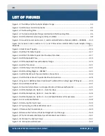
Figure 5-12: Remove the Existing Transducer ......................................................................................... 5-42
Figure 5-13: Mount the New Transducer................................................................................................. 5-43
Figure 6-1: Manual Remote Desktop Credentials for Customer Supplied Computer ............................. 6-44
Figure 6-2: Sonar 192.9.0.101 Remote Desktop Connection Window .................................................... 6-45
Figure 6-3: Sonar 192.9.0.101 Remote Desktop Connection Window .................................................... 6-46
Figure 6-4: Serial Port Information Window ............................................................................................ 6-47
Figure 6-5: Sensor Usage Percentage Check ............................................................................................ 6-48
Figure 6-6: System Status Window .......................................................................................................... 6-49
Figure 8-1: No Sound Velocity on Port 4 .................................................................................................. 8-51
Figure 8-2: Sonar 192.9.0.101 Remote Desktop Connection Window .................................................... 8-51
Figure 8-3: Closing the Sonar.exe Application ......................................................................................... 8-52
Figure 8-4: Connecting to COM4 using TeraTerm ................................................................................... 8-52
Figure 8-5: COM4 Port Settings ............................................................................................................... 8-53
Figure 8-6: Scrolling SV Data in Sonar.exe ............................................................................................... 8-54
Figure 8-7: Configuration Menu ............................................................................................................... 8-55
Figure 8-8: Auxiliary Sensors .................................................................................................................... 8-55
Figure 8-9: Sonar Control Tab .................................................................................................................. 8-56
Figure 8-10: SonarSer-all.ini ..................................................................................................................... 8-57
Figure 8-11: Sonar Remote Desktop Application, Main Screen ............................................................... 8-58
Figure 8-12: Finding the SonarSerial.ini File ............................................................................................ 8-59
Figure 8-13: SonarSerial.ini File ............................................................................................................... 8-59
Figure 8-14: Diagnostic Window, Reporting Ports Inactive Error ............................................................ 8-60
Figure 8-15: Rebooting Sonar from the Main Screen .............................................................................. 8-61
Figure 8-16: Checking Serial Port Information ......................................................................................... 8-62
Figure 8-17: Checking Sensor Status ........................................................................................................ 8-62
Figure 8-18: Closing the System Status Window ..................................................................................... 8-63
Figure 8-19: SonarSerial.ini File ............................................................................................................... 8-64
Figure 8-20: Checking Sensors’ Usages .................................................................................................... 8-66
Figure 8-21: All Sensors Set ...................................................................................................................... 8-67
Figure 8-22: Checking all COM Ports ........................................................................................................ 8-69
Figure 8-23: UDP Configuration Example ................................................................................................ 8-70
Figure 8-24: POSMV UDP Configuration .................................................................................................. 8-72
Figure 8-25: SonarConfig.ini Example ...................................................................................................... 8-73
Figure 8-26: TimeSyncSource Keyword Adjustments .............................................................................. 8-73
Summary of Contents for 6205S
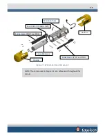
Page 37: ...3 20 Figure 3 5 6205s Exploded View with Adaptor Flange...
Page 38: ...3 21 Figure 3 6 6205s Transducer...
Page 40: ...3 23 Figure 3 8 6205s Wiring Diagram 0019627...
Page 86: ...8 69 Figure 8 22 Checking all COM Ports...
Page 92: ...8 75 Figure 8 28 UDP broadcast settings example Figure 8 29 Eth1 data output...
Page 94: ...8 77 Figure 8 31 1PPS settings example Falling Edge and 1msec duration...


