6-46
6205s BATHYMETRIC AND SIDE SCAN SONAR
0020300_REV_E
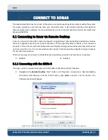
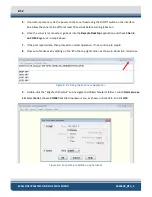
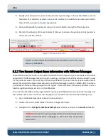
Figure 6-3: Sonar 192.9.0.101 Remote Desktop Connection Window
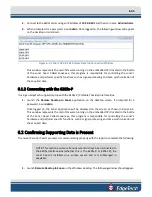
2.
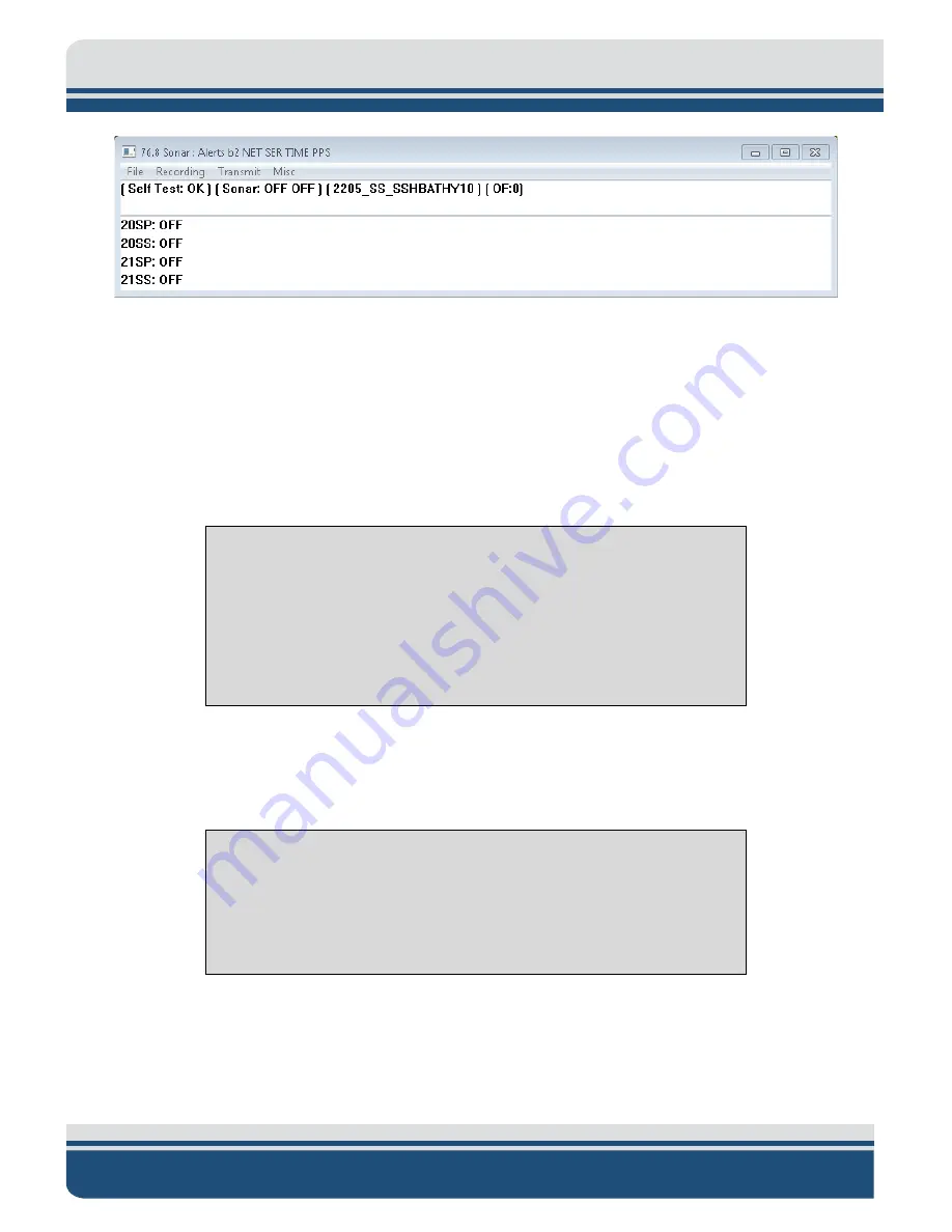
Click on
Menu
>
Misc
>
Serial Port Information
.
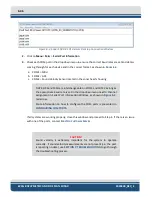
3.
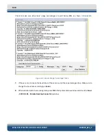
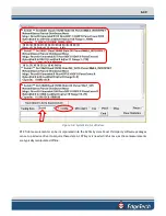
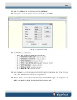
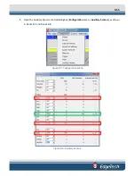
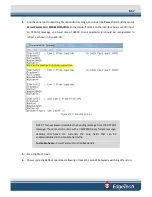
Check each COM port in the dropdown menu to ensure the correct baud rates are set and data is
coming through for each device and in the correct format, as shown in
a.
COM1 = MRU
b.
COM2 = GPS
c.
COM4 = Sound Velocity Sensor located in the sonar head’s housing
NOTE:
GPS and MRU are interchangeable on COM1 and COM2 as long as
the appropriate baud rate is set in the dropdown menu next to channel
assignment in Serial Port Information Window, as shown in
red arrow.
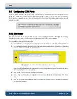
More information on how to configure the COM ports is presented in
CONFIGURING
COM
PORTS.
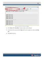
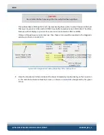
If all systems are working properly, close this window and proceed to Step 4. If there is an issue
with one of the ports, contact
CAUTION!
Sound velocity is extremely important for the system to operate
correctly. If sound velocity measurements are not present (i.e., the port
the troubleshooting process.
Summary of Contents for 6205S
Page 37: ...3 20 Figure 3 5 6205s Exploded View with Adaptor Flange...
Page 38: ...3 21 Figure 3 6 6205s Transducer...
Page 40: ...3 23 Figure 3 8 6205s Wiring Diagram 0019627...
Page 86: ...8 69 Figure 8 22 Checking all COM Ports...
Page 92: ...8 75 Figure 8 28 UDP broadcast settings example Figure 8 29 Eth1 data output...
Page 94: ...8 77 Figure 8 31 1PPS settings example Falling Edge and 1msec duration...

