5-43
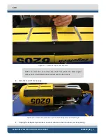
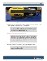
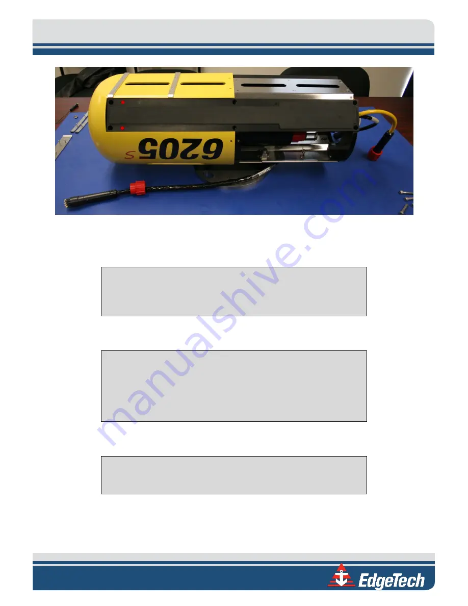
Figure 5-13: Mount the New Transducer
11.
Place the transducer onto the frame and align the screw holes. To keep the transducer in place,
insert two screws on the top and bottom of opposing corners.
NOTE
EdgeTech suggests using a reputable thread lock product to secure
all bolts on the arrays and housing. Contact
to learn what product EdgeTech currently uses.
12.
Repeat the same steps for the opposite transducer.
CAUTION!
Each array is labeled according to the side it corresponds to.
Ensure the port array is installed on the port side and the starboard array
is installed on the starboard side. The sonar processor contains
calibration data specific to each array, and these must be installed
correctly for calibration to be successful.
13.
Complete the transducer installation by completing the steps above in reverse.
NOTE
EdgeTech suggests using a reputable thread lock product to secure
all bolts on the arrays and housing.
Summary of Contents for 6205S
Page 37: ...3 20 Figure 3 5 6205s Exploded View with Adaptor Flange...
Page 38: ...3 21 Figure 3 6 6205s Transducer...
Page 40: ...3 23 Figure 3 8 6205s Wiring Diagram 0019627...
Page 86: ...8 69 Figure 8 22 Checking all COM Ports...
Page 92: ...8 75 Figure 8 28 UDP broadcast settings example Figure 8 29 Eth1 data output...
Page 94: ...8 77 Figure 8 31 1PPS settings example Falling Edge and 1msec duration...

