4-31
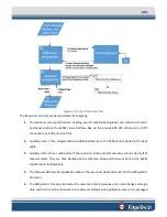
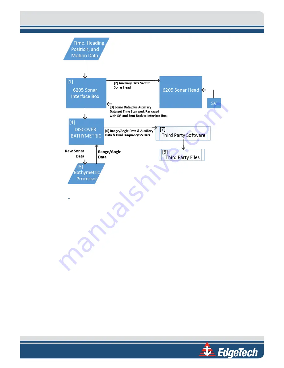
Figure 4-4: Sonar Data Flowchart
The flow chart in
1.
The auxiliary sensors provide time, heading, position (latitude/longitude), and motion (roll, pitch,
and heave) data to the 6205s Sonar Interface Box via the provided RS-232 serial ports or UDP
connections over the ethernet link.
2.
Auxiliary data is then relayed without additional latency to the 6205s Sonar Head via the deck
cable.
3.
Auxiliary data is then combined with the raw sonar data and instantaneous sound velocity (SV)
measurements. They are time-stamped with a common value and then sent back to the 6205s
topside Sonar Interface Box.
4.
The Discover Bathymetric application takes in the raw sonar data and sends it to the Bathymetric
Processor.
5.
The Bathymetric Processor processes the raw sonar data to produce uncorrected range and angle
data and then transmits this back to the Discover Bathymetric application, where it is packaged
Summary of Contents for 6205S
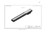
Page 37: ...3 20 Figure 3 5 6205s Exploded View with Adaptor Flange...
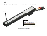
Page 38: ...3 21 Figure 3 6 6205s Transducer...
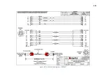
Page 40: ...3 23 Figure 3 8 6205s Wiring Diagram 0019627...
Page 86: ...8 69 Figure 8 22 Checking all COM Ports...
Page 92: ...8 75 Figure 8 28 UDP broadcast settings example Figure 8 29 Eth1 data output...
Page 94: ...8 77 Figure 8 31 1PPS settings example Falling Edge and 1msec duration...

