2-9
2.1.5
Sonar Arrays
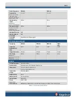
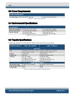
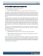
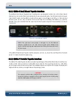
The 6205s provides single frequency bathymetry and simultaneous dual-frequency side-scan sonar.
The side-scan sonar operates at 230/550 kHz, 540/850, or 550/1600 kHz and collects simultaneously on
both frequency channels. Bathymetry is obtained on either the 230 kHz or the 550 kHz. The 6205s utilizes
two arrays (port and starboard) to map the seafloor, much like a dual-head multi-beam system. Each
6205s array is constructed using ten independent longitudinal PZT elements and two multi-segment PZT
strings. The two multi-element strings (one per side scan frequency) are used for the transmit function
and as a full resolution side-scan receiver. The remaining ten elements make an approximately half-
wavelength spaced array of sensors for its bathymetry receiver.
2.1.6
Acoustic Center
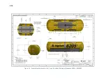
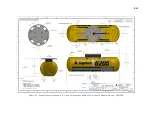
The individual acoustic centers of each array (port and starboard) converge at a single point along the
centerline of the 6205s Sonar Head. Therefore, when entering sonar head offsets into the third-party
acquisition and processing software, the port and starboard array offsets (or sometimes referred to as
Sonar Head 1 and Sonar Head 2, respectively) are identical in all dimensions.
The EdgeTech convention for X, Y, and Z are:
•
X is positive to starboard
•
Y is positive forward
•
Z is positive down
Remember that the individual acoustic centers for both port and starboard converge on the centerline (or
X = 0).
NOTE:
The acoustic center along the y-axis is different for the 230kHz
model than the 550kHz model.
For a larger representation of
Summary of Contents for 6205S
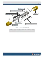
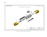
Page 37: ...3 20 Figure 3 5 6205s Exploded View with Adaptor Flange...
Page 38: ...3 21 Figure 3 6 6205s Transducer...
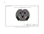
Page 40: ...3 23 Figure 3 8 6205s Wiring Diagram 0019627...
Page 86: ...8 69 Figure 8 22 Checking all COM Ports...
Page 92: ...8 75 Figure 8 28 UDP broadcast settings example Figure 8 29 Eth1 data output...
Page 94: ...8 77 Figure 8 31 1PPS settings example Falling Edge and 1msec duration...

