background image

33  |  ZincBlue2 User Manual

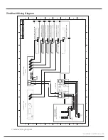
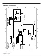
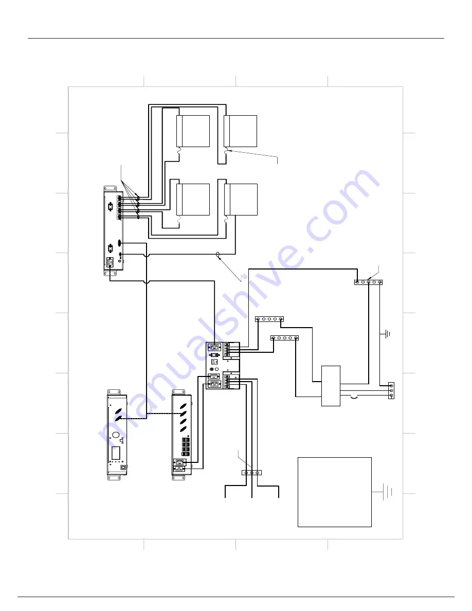
ZincBlue2 XRT Wiring Diagram

MONOBLOC

BATTERY 80 Ah 15.2V MAX

-

+

MONOBLOC

BATTERY 80 Ah 15.2V MAX

-

+

MONOBLOC

BATTERY 80 Ah 15.2V MAX

-

+

MONOBLOC

BATTERY 80 Ah 15.2V MAX

-

+

4X DC POWER

INTERCONNECT CABLE

ZincBlue2 XRT IMS 

FRONT VIEW

EXT. TEMPERATURE

SENSOR

ZincBlue2

UPS 1000W/1500W 

FRONT VIEW

ZincBlue2

UPS 1000W/1500W

REAR VIEW

PIM

AC-

GND

AC+

GND

AC-

AC+

L

G

N

30A

30A CIRCUIT

BREAKER MAINS

TERMINAL BAR BONDED TO

CABINET

DOOR

G

N

L

L

N

G

L

N

UTILITY POWER INPUT

TO NEUTRAL

BUSS

TO EQ GND

TO CABINET EQUIPMENT AC INPUT

40A INLINE FUSE ON EACH BATTERY

SURGE PROTECTION

(OPTIONAL)

A

A

B

B

C

C

D

D

8

8

7

7

6

6

5

5

4

4

3

3

2

2

1

1

ZincBlue2 XRT Wiring Diagram

Summary of Contents for ZincBlue2 UPS 1000W

Page 1: ...ZincBlue2 Manual...

Page 2: ...This user manual provides the essential information you need in order to get the most from your ZincBlue2 Uninterruptible Power Supply ZincBlue2 Software Copyright 2021 Econolite All rights reserved...

Page 3: ...31 Sch ma de c blage d ZincBlue2 32 Wiring the ZincBlue2 XRT 32 Connecting ZincBlue2 XRT to UPS and PIM 32 Installing Additional ZincBlue2 XRT Battery 3600Wh 33 ZincBlue2 XRT Wiring Diagram ZincBlue2...

Page 4: ...limentation en courant continu 29 C ble d interconnexion num rique et d alimentation en courant continu 29 Verrouillage du c ble d interconnexion d alimentation en courant alternatif 29 C ble d alimen...

Page 5: ...orks of the manufacturer Trademarks ZincBlue is a registered trademark of Econolite Use of third party trademarks brand names trade names and or prod uct names are for informational purpose only and a...

Page 6: ...t www econolite com support or call 800 225 6480 ZincBlue2 Recycling Econolite cares about our environment and has made arrangements for users to easily recycle all ZincBlue2 components including the...

Page 7: ...f liquid enter the UPS and batteries Do not operate the UPS and batteries with damaged cables and wires Defective cables and wires must be replaced before system installation Prior to system installat...

Page 8: ...done or supervised by personnel knowledgeable about batteries and the required precautions Battery Panel Module must not be installed in a sealed enclosure ventilation must be provided Use proper lif...

Page 9: ...s endommag s Les c bles et fils d fectueux doivent tre remplac s avant l installation du syst me Avant l installation du syst me v rifier que tous les c bles et fils sont correctement fix s et connect...

Page 10: ...ge 120Vac Nominal 85 140Vac User Programable Input Current 15A max Input Frequency 60Hz nominal 10 54 66Hz Output Voltage 120Vac 3 Output Current 8 3A Typical Output Power 1 000VA Typical Output Frequ...

Page 11: ...s pre event and 250ms post event sine cycles along with a day date time stamp in the event log Up to 1000 events with waveforms can be stored in the event log and accessed through the browser based Zi...

Page 12: ...SAVE funtion 7 NAVIGATION DIAL Rotating navigation dial for control of the LCD screen cursor Pushing the dial functions as a Select button 8 BATTERY INPUTS Six 6 battery inputs for connecting battery...

Page 13: ...een the Battery and PIM Use the provided Locking AC Power Interconnect Cable 4 HANDLE Used for lifting the battery panel 5 STATUS A multi color LED indicators that provides battery status Green Backup...

Page 14: ...tartup of an intersection With the monobloc nickel zinc batteries connected push and hold for 5 8 seconds for immediate system cold startup Hold for 10 20 seconds to turn off 2 BATTERY OUTPUT The conn...

Page 15: ...charge mode Red Green Alternating Weak battery detected discharge mode 6 MICRO USB PORT Reserved for manufacturer use 7 AC POWER A 20Amp Breaker to turn AC ON OFF 8 BATTERY TEMPERATURE Battery Tempera...

Page 16: ...un module de batterie connect l ASC appuyer et maintenir pendant 5 secondes pour un d marrage froid imm diat du syst me Maintenir pendant 10 secondes pour l teindre 2 SORTIE DE LA BATTERIE Le point de...

Page 17: ...onnecter le c ble CA la nouvelle batterie Le d branchement des piles puis es avant de brancher des piles neuves peut entra ner l arr t pr matur du syst me lorsqu il est en mode de d charge Lorsque le...

Page 18: ...OAD 20A breaker protection for the load 7 UPS TEST 15A breaker switch on incoming utility AC power In the ON position the AC from utility input is connected to the ZincBlue2 UPS 1000W 1500W providing...

Page 19: ...packaging The ZincBlue2 system should be installed in a restricted access environment and only installed and serviced by authorized personnel Tools Needed Slotted screwdriver 1 8 and 3 16 1 8 used for...

Page 20: ...e on Disconnect the ZincBlue2 UPS 1000W 1500W from AC Power and adjust the rack or shelf mounting so that the device does not tilt in excess of 15 degrees from level Then connect AC Power back to the...

Page 21: ...own in the below figures The space bar and speedy sleeve will assist with installation use the provided figures and steps to install the ZincBlue2 Battery Panel Step 1 Spacer Bar Insert the spacer bar...

Page 22: ...placed on a shelf For shelf installations no other hardware is needed For rack installation use the provided bracket 1 and screws 4 as shown in the figure below Battery Module Rack Mount Installation...

Page 23: ...st me ZincBlue2 doit tre install dans un environnement acc s restreint et ne doit tre install et entretenu que par du personnel autoris Outils requis Tournevis fente 1 8 po et 3 16 po 1 8 po utilis po...

Page 24: ...e ZincBlue2 500 W Le module de batterie ZincBlue2 est install par montage en tag re ou en rack Pour une installation d tag re aucun autre mat riel n est n cessaire Pour l installation en rack utiliser...

Page 25: ...terconnect Cable to allow wall outlet charging of Battery Panel and Module QTY 1 Length 48 to 6 10 split Cable used to daisy chain AC Power between batteries QTY 1 Length 6ft Cable used to interconnec...

Page 26: ...erly attached to the wires The correct torque for the terminals is 16 in lbs Note A Listed Type 1 or Type 2 Surge Protective Device having a VPR rating maximum 1500 Vpk transient voltage shall be prov...

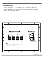
Page 27: ...connection are CLASS 2 H G F E D C B A 8 7 6 5 4 3 2 1 H G F E D C B A 8 7 6 5 4 3 2 1 H G F E D C B A 8 7 6 5 4 3 2 1 H G F E D C B A 8 7 6 5 4 3 2 1 Common C Normally Open NO Normally Closed NC N No...

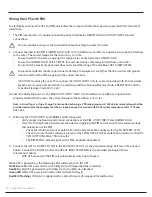
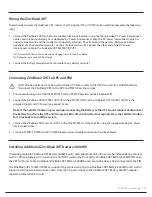
Page 28: ...the TO BATTERY AC IN on the PIM using the supplied Locking AC Power Interconnect Cable and AC Power Daisy Chain Cable as needed When the battery unit is connected to AC the battery unit LED should Wh...

Page 29: ...2 26 18 DW Class 2 Relay connections Class 2 Relay connections AC FROM UPS AC G ND AC AC G ND AC AC GND AC AC GND AC N G L G N L NEUTRAL BUSS EQ GND TO CABINET EQUIP MENT AC INPUT UTILITY POW ER INPUT...

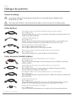
Page 30: ...tilis pour toutes les interconnexions d alimentation en courant alternatif entre l ASC et le MIA et entre le MIA et la batterie QT 1 Longueur 1 pi Adaptateur pour le verrouillage du c ble d interconne...

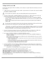
Page 31: ...n de la ligne d utilit au MIA ENTR E UTILITAIRE avec des fils de 10 12 AWG et des bornes anneaux de taille n 8 fix es aux fils Le couple correct pour les terminaux est de 16 in lb 4 Avec seulement l E...

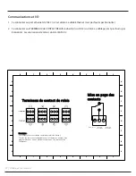
Page 32: ...6 5 4 3 2 1 H G F E D C B A 8 7 6 5 4 3 2 1 H G F E D C B A 8 7 6 5 4 3 2 1 H G F E D C B A 8 7 6 5 4 3 2 1 Common C Normally Open NO Normally Closed NC R Re em ma ar rq qu ue e Les contacts secs sont...

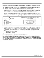
Page 33: ...dre le syst me 2 Connecter l entr e CA du panneau de batterie ou du module de batterie de l ZincBlue2 l entr e CA DE LA BAT TERIE sur le MIA l aide du c ble d interconnexion d alimentation CA verrouil...

Page 34: ...tions Class 2 Relay connections AC FROM UPS AC G ND AC AC G ND AC AC GN D AC AC GN D AC N G L G N L NEUTRAL BUSS EQ GND TO CABINET EQUIP MENT AC INPUT UTILITY POW ER INPUT G N ZincBlue2 UPS 1000W Fron...

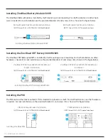
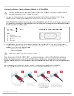
Page 35: ...ER breakers on the ZincBlue2 XRT 2 Connect the ZincBlue2 XRT BATTERY OUTPUT to the BATTERY INPUT of the ZincBlue2 UPS 1000W 1500W via the provided Digital and DC Power Interconnect Cable Note If the C...

Page 36: ...MS FRONT VIEW EXT TEMPERATURE SENSOR ZincBlue2 UPS 1000W 1500W FRONT VIEW ZincBlue2 UPS 1000W 1500W REAR VIEW PIM AC GND AC GND AC AC L G N 30A 30A CIRCUIT BREAKER MAINS TERMINAL BAR BONDED TO CABINET...

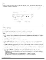
Page 37: ...supplying backup power and the batteries are below 10 capacity The green LED will flash at a frequency of twice per second RELAY TRIGGERED Solid Yellow The solid yellow LED will be ON any time one of...

Page 38: ...NOR MAL status CAPACITY Total remaining capacity of all attached batteries from 100 completely charged to 0 completely discharged BATTERY ATTACHMENT DIAGRAM A series of six circles to indicate the si...

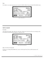
Page 39: ...UPS 1000W 1500W switches from Utility power to Battery power the top line of the main status display will be STATUS BACKUP This indicates that the ZincBlue2 is using battery power Notes STATUS BACKUP...

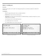
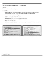
Page 40: ...are numbered sequentially EVENT TYPE Shows the event that caused the log entry TIME STAMP Shows the date and time of the log entry For POWER RESUME logs the duration of elapsed time since the POWER FA...

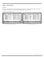
Page 41: ...pty circle indicates that the relay is OFF A filled in circle to the right of a relay indicates that the relay is ON The relay status will continually be updated as long as the screen is visible Press...

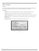
Page 42: ...u to set the UPS date and time clock Also allows configuration of daylight saving time EVENTS Allows you to define edit or delete events Events are a collection of triggers and log events POWER FAIL T...

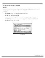
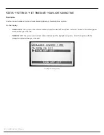
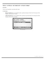
Page 43: ...time stamped with the system time and date On The Display SET TIME FORMAT Allows you to choose 12 hour or 24 hour time display SET TIME Allows you to set the current time DAYLIGHT SAVING TIME Allows y...

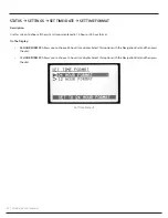
Page 44: ...me is displayed in 12 hour or 24 hour format On The Display 24 HOUR FORMAT Allows you to choose 24 hour time display Select this option with the Navigation Dial and then press the dial 12 HOUR FORMAT...

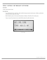
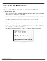
Page 45: ...Dial to select hours rotate the dial to increment or decrement the hours and then press the dial to set the hours value and select the minutes Rotate the dial to increment or decrement the minutes an...

Page 46: ...aylight saving time On The Display TURN ON DST The system clock will automatically adjust for daylight saving time Select this option with the Navigation Dial and then press the dial TURN OFF DST The...

Page 47: ...format On The Display MM DD YY FORMAT Allows you to display the date using the month day year format Select this option with the Navigation Dial and then press the dial YY MM DD FORMAT Allows you to...

Page 48: ...nt the day 01 31 and then press the dial to set the day value and select the year Rotate the dial to increment or decrement the year 00 99 and then press the dial to set the year value To Set the Date...

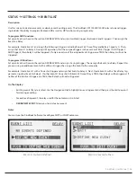
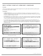
Page 49: ...not be triggered To program OR functions Set up an Event as shown in the section DEFINE EVENT and assign it a single trigger Then assign the Event to a Relay Repeat this process using an additional E...

Page 50: ...allows you to adjust the delay time after a power failure before the trigger is activated SYSTEM FAULT Enable the System Fault trigger TIME Allows you to configure the time of day trigger BATTERY CAPA...

Page 51: ...ine a delay time in hours after a power failure before this trigger becomes TRUE The delay time is set in increments of 0 5 hours to a maximum of 8 0 hours The default value if none is specified is 0...

Page 52: ...d by the ZincBlue2 Software On The Display Press the BACK button when you are finished configuring this trigger You will be taken back to the DEFINE EVENT screen where you can configure additional tri...

Page 53: ...me in 5 minute increments Use the Navigation Dial to highlight END rotate the dial to select the end time and then press the dial to set the value Press the BACK button when you are finished configuri...

Page 54: ...igger will be TRUE Use the Navigation Dial to highlight BATTERY CAPACITY rotate the dial to select the percentage and then press the dial to set the value Press the BACK button when you are finished c...

Page 55: ...ent created through the LCD interface on the ZincBlue2 You must use the ZincBlue2 Software to configure SMTP or SNMP notifications On The Display Use the Navigation Dial to highlight the relay to use...

Page 56: ...ssing the BACK button from the DEFINE EVENT screen the EVENT SAVE CONFIRMATION screen will prompt you to save your event On This Display The system creates an event name consisting of one or more of t...

Page 57: ...ET HIGH THRESHOLD Allows you to specify the maximum utility AC voltage threshold If utility voltage goes above this threshold the ZincBlue2 will switch to battery power ENHANCED SENSITIVITY When choos...

Page 58: ...1000W 1500W will switch to battery power On The Display LOW THRESHOLD Allows you to specify the minimum utility AC voltage before the ZincBlue2 will switch to battery power Rotate the Navigation Dial...

Page 59: ...1000W 1500W will switch to battery power On The Display HIGH THRESHOLD Allows you to specify the maximum utility AC voltage before the ZincBlue2 will switch to battery power Rotate the Navigation Dial...

Page 60: ...F Turn the Navigation Dial to turn ON or OFF enhanced sensitivity and then press the dial to set the value OFF sensitivity is selected by default Press the BACK button when you are finished configurin...

Page 61: ...cycling noisy power or power frequency mismatches after a utility power failure On The Display SECONDS Allows you to select the time period in seconds that the utility power must be within quality par...

Page 62: ...rent IP address The default IP address is 192 168 1 51 and may only be changed using the ZincBlue2 Software MAC ADDRESS Displays the MAC address of the ZincBlue2 This value is not user changeable Pres...

Page 63: ...n after selecting this option Press the Navigation Dial to confirm your request CONFIG AND FIRMWARE Resets the ZincBlue2 configuration data to factory default values reloads the originally installed f...

Page 64: ...ctory programmed to have the Tilt Switch disabled off which is displayed on the screen TILT ON Rotate the Navigational Dial left right to enable the Tilt Switch function Press the Navigational Dial to...

Page 65: ...splay the firmware version and whether the Tilt Switch function if avilable On The Display FW REVISION Displays the current firmware version TILT SWITCH AVAILABLE Displays on screen if enabled POWER R...

Page 66: ...attery charge status and runtimes View real time cabinet power consumption Configure Simple Network Management Protocol SNMP communication to be notified of system status Assign a name to a ZincBlue2...

Page 67: ...Click on Network and Internet Click on Ethernet Change Adapter Options Select an ethernet port right click and select Properties Find and select Internet Protocol Version 4 TCP IPv4 Click Properties...

Page 68: ...ogin screen When this screen appears enter your username and password and click the Login button IMPORTANT Each ZincBlue2 comes with the preset username admin and the preset password user System will...

Page 69: ...ens a page used to view captured events RELAY STATUS opens a summary page showing the 8 relays and whether they are triggered on or off EVENTS opens a page used to configure or edit events that you wa...

Page 70: ...that have taken place in the traffic cabinet For each event the main view lists the event s log number the event source a time stamp showing when the event occurred an error message the system ID and...

Page 71: ...of Specification AC Wiring Error Controller Temperature out of specification Inverter Locked out Excessive Load System Shutdown Battery Charger Firmware Updated System Config Change Time Format System...

Page 72: ...69 ZincBlue2 User Manual Relay Status Tab The Relay Status tab shows the status of the eight user programmable relays on the UPS indicating whether each is on or off Relay Status Tab...

Page 73: ...The tab displays a list of Events and clickable actions like Add Event and Delete Event buttons and No Event Configured Please Click here to add one To delete an existing event select that event in t...

Page 74: ...ect and remove triggers or add new ones 3 You will be asked to define an event outcome If there are no outcomes defined for the event there will be a button to click to add one If there are outcomes y...

Page 75: ...power signal must be within quality parameters before the system comes out of backup mode The options for this setting are 3 10 or 30 seconds If the UPS detects unacceptable AC power quality within th...

Page 76: ...users to log in to a specific ZincBlue2 Gateway Address Sets the IP address of the gateway that the ZincBlue2 will use Subnet Sets the subnet that the ZincBlue2 unit will be on DHCP enabled Check thi...

Page 77: ...le If you update your firmware but then introduce a new battery to the configuration you will need to update the battery firmware as well To update the Firmware and Software for ZincBlue2 visit the Ec...

Page 78: ...entries or in the ZincBlue2 application will be automatically adjusted to be consistent with the unit s local time The Enable Daylight Saving Time checkbox sets the ZincBlue2 unit to automatically ad...

Page 79: ...t password user To reset the password you will be asked to enter the old pass word and the new password then re enter the new password to confirm Passwords can be up to 32 characters long and contain...

Page 80: ...tbeat messages to indicate the system is still powered on and able to notify the SNMP server that it is able to communicate Event Destination Email Address Email address where event messages will be s...

Page 81: ...tage frequency and waveform anomalies When the pre defined or user defined AC thresholds are exceeded the ZincBlue2 UPS 1000W 1500W will transfer from AC Utility power to battery backup The ZincBlue2...

Page 82: ...discharge These devices communicate via CAN bus across the battery Digital and DC Power Interconnect Cable with the ZincBlue2 UPS 1000W 1500W Upon loss of power the ZincBlue2 UPS 1000W 1500W will sig...

Page 83: ...so lated via conduit input hole and cover The terminal blocks can accept 10 12 AWG wire using a ring terminal or spade terminal The UPS TEST switch on the PIM can be utilized to test the ZincBlue2 UPS...

Page 84: ...service or the battery temperature senor cable is unplugged The ZincBlue2 XRT uses several different modes which include Constant Current and Constant Voltage to optimize charging and balancing the b...

Page 85: ...ED 3 If a RUN TIME test is desired it is best to leave the UPS TEST switch in the ON position and turn off the utility power off at the breaker going to the PIM This will force the ZincBlue2 UPS 1000W...

Page 86: ...h initialization and startup of the inverter If this continues check battery connection batteries maybe missing An invalid Subnet Mask was entered making it impossible to connect with UPS 1000 If an i...

Page 87: ...are no warranties for loss of data No other warranties are expressed or implied 4 This Limited Warranty only applies to defects which may have arisen from system failures related to components or wor...

Page 88: ...tended warranty can be purchased at time of original purchase on a per year basis up to three additional 3 years 11 Written authorization for the warranty return of merchandise RMA must be obtained fr...

Page 89: ...ndth of a second NC Normally Closed Contact circuit completed NEMA National Electrical Manufacturers Association Nickel Zinc Rechargeable battery chemistry that uses Nickel and Zinc NiZn NO Normally O...

Page 90: ...87 ZincBlue2 User Manual Notes...

Page 91: ...This user manual provides the essential information you need in order to get the most from your ZincBlue2 Uninterruptible Power Supply ZincBlue2 Software Copyright 2021 Econolite All rights reserved...

Page 92: ...Econolite 1250 N Tustin Ave Anaheim CA 92807 www econolite com support 01100 00200 00030 rev H07 Copyright 2021 Econolite All rights reserved...

Reviews: