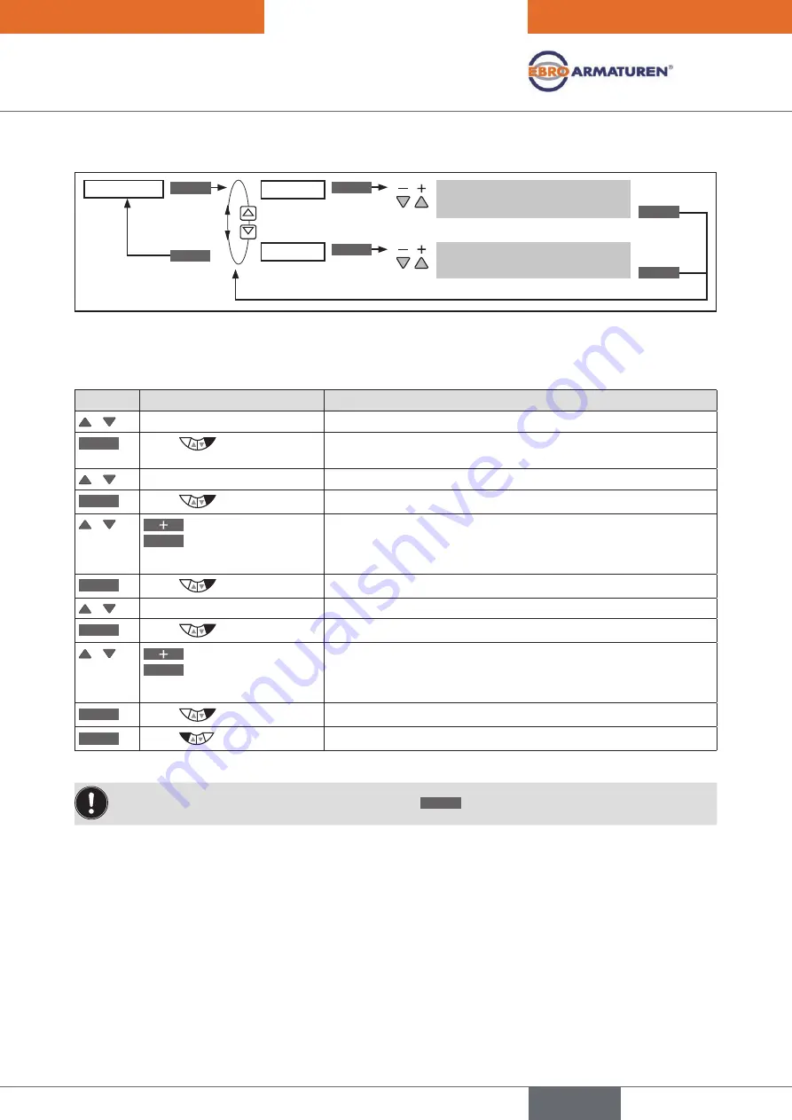
background image

75

Typ EP 501

Start-Up

Operating structure:

*

ENTER

INPUT

INPUT

OK

OK

EXIT

SP-SCALE

SPmin

SPmax

Input upper process set-point 
value

Input lower process set-point 
value

*

Figure 31: 

Operating structure SP-SCALE

Scaling.process.set-point.value.

SETUP

.

.

SP-SCALE

:

Key

Action

Description

 /   

Select

 SP-SCALE

ENTER

Press 

The submenu options for scaling of the process set-point value are 
displayed.

 /   

Select

 SPmin

INPUT

Press 

The input screen is opened. 

 /   

 Increase value 

<–

 Select decimal place

Set scaling value (lower process set-point value).

The value is assigned to the smallest current or voltage value of the 
standard signal.

OK

Press 

Return to 

SP-SCALE.

 /   

Select

 SPmax

INPUT

Press 

The input screen is opened.

 /   

 Increase value 

<–

 Select decimal place

Set scaling value (upper process set-point value). 

The value is assigned to the largest current or voltage value of the 
standard signal.

OK

Press 

Return to 

SP-SCALE.

EXIT

Press 

Return to 

SETUP. 

Table 34: 

SP-SCALE; scaling process set-point value

If the submenu is left by pressing the left selection key 

ESC

, the value remains unchanged.

english

Summary of Contents for EP 501 C

Page 1: ...Operating Instructions Type EP 501 Electropneumatic positioner and process controller...

Page 2: ...We reserve the right to make technical changes without notice Technische nderungen vorbehalten Sous r serve de modification techniques Operating Instructions 1710 01_EU en_00810559 Original DE...

Page 3: ...ss controller 26 11 Technical data 27 INSTALLATION 33 12 Attachment and assembly 34 13 Pneumatic connection 39 14 Electrical connection Terminal version for cable gland 41 OPERATION 45 15 Operating le...

Page 4: ...ntenance 184 30 Error messages and malfunctions 184 PACKAGING STORAGE DISPOSAL 188 31 Packaging and transport 189 32 Storage 189 33 Disposal 189 ADDITIONAL TECHNICAL INFORMATION 190 34 Selection crite...

Page 5: ...ASIC SAFETY INSTRUCTIONS 8 4 USE IN THE EX AREA 9 4 1 Basic safety instructions for use in the Ex area 9 4 2 Safety instructions for the installation and maintenance of Ex devices 9 5 GENERAL INFORMAT...

Page 6: ...or serious injury DANGER Warns of an immediate danger Failure to observe the warning may result in a fatal or serious injury WARNING Warns of a potentially dangerous situation Failure to observe the...

Page 7: ...ing use observe the permitted data the operating conditions and conditions of use specified in the con tract documents and operating instructions as described in chapter Description of System 11 Techn...

Page 8: ...ated only when in perfect condition and in consideration of the operating instructions Do not supply the supply pressure connection of the system with aggressive or flammable mediums Do not supply the...

Page 9: ...nce of Ex devices DANGER Risk of explosion To prevent the risk of explosion observe the following during installation and maintenance in the Ex area Do not open the device housing To avoid electrostat...

Page 10: ...ren com International The international contact addresses can be found on the internet at www ebro armaturen com 5 3 Warranty The warranty is only valid if the device is used as intended in accordance...

Page 11: ...OSITIONER TYPE EP 501 17 8 1 Schematic representation of the position control 18 8 2 Positioner software 19 9 PROCESS CONTROLLER TYPE EP 501 C 21 9 1 Schematic representation of process control 22 9 2...

Page 12: ...12 Typ EP 501 Description of System 11 8 Safety end positions after failure of the electrical or pneumatic auxiliary power 31 11 9 Factory settings 32 english...

Page 13: ...contact non wearing position sensor remote Microprocessor controlled electronics for signal processing control and valve control Operating module Operation of the device is controlled by four keys Th...

Page 14: ...r in the attachment option and in the position sensor Device version NAMUR An internal position sensor is used which is designed as a rotary potentiometer The device is mounted directly on the actuato...

Page 15: ...phics display The pneumatic control system for single acting and double acting actuators consists of 2 solenoid valves 7 1 Representation Pressure relief valve Mechanical position indicator Operating...

Page 16: ...tem 1 Aeration valve 2 Bleed valve Compressed air supply Position sensor Process controller Positioner Control system 1 2 Process set point value Process actual value Position set point value Exhaust...

Page 17: ...ard signal If there is a control dif ference Xd1 the actuator is aerated and deaerated via the control system In this way the position of the actuator is changed until control difference is 0 Z1 repre...

Page 18: ...Schematic representation of the position control 4 20 mA 0 20 mA 0 10 V 0 5 V DIR CMD SPLTRNG CHARACT CUTOFF X TIME DIR ACT X LIMIT X CONTROL DBND POS CMD INP POS CMD TEMP INPUT Figure 4 Schematic rep...

Page 19: ...r more positioners Stroke limit X LIMIT Mechanical valve piston movement only within a defined stroke range Limiting the control speed X TIME Input of the opening and closing time for the entire strok...

Page 20: ...tion software SIMULATION For simulation of the device functions DIAGNOSE Option Monitoring of processes Table 1 Positioner software Configurable auxiliary functions Hierarchical operating concept for...

Page 21: ...nt position POS of the pneumatic actuator The positioner compares this actual position value with the set point value CMD which is determined by the process controller If there is a control difference...

Page 22: ...n of process control 4 20 mA 0 20 mA 0 10 V 0 5 V DIR CMD CHARACT CUTOFF X TIME DIR ACT X LIMIT X CONTROL DBDx POS CMD PV POS CMD PV SP TEMP PV SCALE PV SP SCALE SP SP P CONTROL PARAMETER SETUP Q FILT...

Page 23: ...Type EP 501 L Interface Sensor Setting in the menu ADD FUNCTION Positioner position controller analog 4 20 mA Any high resolution path sensor POS SENSOR ANALOG For menu description see 24 2 19 POS SEN...

Page 24: ...limit X LIMIT Mechanical valve piston movement only within a defined stroke range Limiting the control speed X TIME Input of the opening and closing time for the entire stroke Insensitivity range X CO...

Page 25: ...s set point value Selection of the set point value defaults Automatic sensor detection or manual sensor setting P CONTROL SETUP PV INPUT Sensor types Pt100 and 4 20 mA are automatically detected or ca...

Page 26: ...ner Process controller 2 binary outputs 24 V PNP Initiator 1 Initiator 2 24 V PNP NO Analogue feedback 4 20 mA 0 10 V Inputs Outputs Supply Operation Note Optional inputs and outputs are illustrated b...

Page 27: ...erature does not exceed the maximum value or drop below the minimum value Environmental temperature The permitted temperature range is given on the type label of the device Degree of protection IP 65...

Page 28: ...T4 II 3 D Ex tD A22 T135 C Warning 1 Do not open under explosive atmosphere 2 In Hazardous Areas the surface may only be cleaned with a wet towel Figure 9 Additional plate for Ex devices 11 5 Mechanic...

Page 29: ...triangle Pt 100 Measuring range 20 220 C Resolution 0 1 C Measurement current 1 mA Input data for set point value signal 0 4 20 mA Input resistance 180 Resolution 12 bit 0 5 10 V Input resistance 19 k...

Page 30: ...r min 10 degrees below the lowest operating temperature Oil content Class X max 25 mg m Temperature range of compressed air 0 60 C Pressure range 1 4 7 bar Air flow rate 95 lN min at 1 4 bar for aerat...

Page 31: ...according to Figure 10 up down Connection according to Figure 11 up down lower chamber upper chamber double acting Control function I connection see Figure 12 not defined up lower chamber of the actu...

Page 32: ...ings page 156 The factory presets are highlighted in blue to the right of the menu in the operating structure Examples Representation Description Menu options activated or selected at the factory Menu...

Page 33: ...s 39 14 ELECTRICAL CONNECTION TERMINAL VERSION FOR CABLE GLAND 41 14 1 Connection board of the Type EP 501 EP 501 C with screw type terminals 42 14 2 Terminal assignment for cable gland positioner Typ...

Page 34: ...with rotary actuator The shaft of the position sensor integrated in the positioner is connected directly to the shaft of the rotary actuator 12 2 1 Installation WARNING Risk of injury from improper in...

Page 35: ...r the swing range of the flattened shaft min 30 max 180 The swing movement of the flattened shaft must be within the position sensor rotation range of 180 Flattened shaft 180 Maximum swing range Figur...

Page 36: ...attachment If the X TUNE ERROR 5 message is indicated on the graphics display after the X TUNE function starts the shaft of the device is not correctly aligned with the shaft of the actuator see Tabl...

Page 37: ...sensor In principle any path sensor with a 4 20 mA output can be connected which has an adequate resolution of the path signal Good control properties are obtained if the resolution of the path sensor...

Page 38: ...ct Type EP 501 L pneumatically to the actuator Switch on Type EP 501 L operating voltage To obtain the best possible control precision adjust the path sensor so that path to be measured corresponds to...

Page 39: ...ion Installation may be carried out by authorized technicians only and with the appropriate tools Risk of injury from unintentional activation of the system and an uncontrolled restart Secure system f...

Page 40: ...orking connections A1 and A2 to the respective chambers of the double acting actuator see chapter 11 8 Safety end positions after failure of the electrical or pneumatic auxiliary power Important infor...

Page 41: ...lation instructions supplied by the cable gland manufacturer Before start up in the Ex area check whether the cable gland was installed as described in these installation instructions Close all unnece...

Page 42: ...erminal assignment for cable gland positioner Type EP 501 for Type EP 501 C chapter 14 3 Terminal assignment for cable gland process controller Type EP 501 C 14 2 Terminal assignment for cable gland p...

Page 43: ...ltage GND terminal GND 85 Binary output 2 85 24 V 0 V NC NO specific to operating voltage GND terminal GND 31 Analogue feedback 31 0 4 20 mA or 0 5 10 V completely galvanically isolated 32 Analogue fe...

Page 44: ...ally supplied actual value 1 24 V sensor supply 1 24 V 2 Clock input 2 Clock 3 not used 4 Clock input 4 GND GND from operating voltage GND Clock GND Frequency externally supplied actual value 1 not us...

Page 45: ...8 16 2 Function of the keys 49 16 2 1 Entering and changing numerical values 50 16 3 Adjusting the display 51 16 3 1 Possible displays of the process level 51 16 4 Date and time 53 16 4 1 Setting date...

Page 46: ...g the operating parameters Activating auxiliary functions If the device is in the AUTOMATIC operating state when changing to the setting level the process continues running during the setting 15 1 Swi...

Page 47: ...yed Abbreviated designation for the displayed process value Operating elements Process value Unit of the displayed process value Designation for the function of the keys Right selection key Arrow key...

Page 48: ...r AUTOMATIC or MANUAL operating state and the activated functions Operation Symbol Description Types EP 501 EP 501 C Operation as positioner AUTOMATIC operating state Diagnosis active optional only av...

Page 49: ...Change the displayed value e g POS CMD TEMP AUTOMATIC Left selection key MENU Change to the setting level Note Press key for approx 3 s AUTOMATIC or MANUAL Right selection key AUTO Return to AUTOMATIC...

Page 50: ...value When the largest possible value has been reached 0 is displayed again Left selection key ESC or EXIT Return without change Right selection key OK Accept the set value Table 16 Change numerical v...

Page 51: ...0 0 Actual position of the valve actuator 0 100 MENU POS TEMP MANU CMD 0 0 Set point position of the valve actuator or Set point position of the valve actuator after rescaling by possibly activated sp...

Page 52: ...MENU X TUNE P LIN RUN P TUNE Automatic optimization of the process controller parameters Only for Type EP 501 C MENU P TUNE CMD POS RUN P LIN Automatic linearization of the process characteristics Onl...

Page 53: ...s are displayed Select EXTRAS ENTER Press Activate the EXTRAS auxiliary function by marking with a cross and transfer into the main menu MAIN EXIT Press Return to the main menu MAIN Select EXTRAS ENTE...

Page 54: ...ime unit from right to left When the last time unit for the date has been reached the display switches to the time units for the time If the last unit is at top left hours the display switches back to...

Page 55: ...e the valve can be manually opened or closed via the arrow keys key function OPN and CLS The symbol for AUTOMATIC is hidden No bar running along the upper edge of the display The MANUAL operating stat...

Page 56: ...tion ENTER Press The selected auxiliary function is now marked by a cross EXIT Press Acknowledgment and simultaneous return to the main menu MAIN The marked function is now activated and incorporated...

Page 57: ...imultaneous incorporation into the main menu MAIN 18 1 2 Deactivating auxiliary functions Procedure Key Action Description MENU Press for approx 3 s Switching from process level setting level Select A...

Page 58: ...of the valve actuator When switching to MANUAL operating state POS is displayed SP PV process set point value When switching to MANUAL operating state PV is displayed The switch is possible only for...

Page 59: ...xtern 74 23 2 4 SP SCALE Scaling of the process set point value for external set point value default only 74 23 2 5 P CO INIT Smooth switchover MANUAL AUTOMATIC 76 23 3 PID PARAMETER Parameterizing th...

Page 60: ...ocess controller P CONTROL 23 4 Setting the hardware SETUP 23 2 5 Parameter setting of the software PID PARAMETER 23 3 6 Automatic linearization of the process characteristics P Q LIN 23 4 to be imple...

Page 61: ...Press for approx 3 s Hold down as long as countdown 5 is running X TUNE STARTED TUNE 0 INIT X TUNE READY Process level values are displayed Configuration Select the input signal Activating auxiliary...

Page 62: ...UT are displayed Select input signal 4 20 mA 0 20 mA SELEC Press The selected input signal is now marked by a filled circle EXIT Press Return to the main menu MAIN EXIT Press Switching from setting le...

Page 63: ...automatically Adjustment of the sensor signal to the physical stroke of the actuator used Determination of parameters of the PWM signals to control the solenoid valves integrated in Type EP 501 EP 501...

Page 64: ...he main menu MAIN If X CONTROL is not activated a fixed dead band of 1 is used The changed data is saved in the memory EEPROM only when there is a switch to the process level by leaving the main menu...

Page 65: ...te position measurement Set middle position Warning information gives tips on optimized operation The device is operational even if this warning information is not observed Warning information is auto...

Page 66: ...simultaneous return to the main menu MAIN P CONTROL is now activated and incorporated into the main menu Table 28 Activating auxiliary functions Following activation of P CONTROL the P Q LIN and P TUN...

Page 67: ...function is indicated only if the external set point value default external menu option is activated under SP INPUT Figure 25 Operating structure P CONTROL Key Insensitivity range dead band of the PI...

Page 68: ...ntroller is displayed Set up is described in Chapter 23 2 SETUP Setting up the process controller EXIT Press Return to P CONTROL 2 Parameterize process controller Select PID PARAMETER ENTER Press The...

Page 69: ...pe PT 100 or 4 20 mA is detected the signal type is automatically implemented in the PV INPUT operating menu If no sensor signal is detected the last setting is retained The signal type frequency sign...

Page 70: ...tor K factor for the flow sensor The menu option is available only for the frequency signal type PV INPUT Frequency Operating structure ENTER INPUT INPUT INPUT INPUT ENTER OK OK OK START OK STOP EXIT...

Page 71: ...00 800 200 800 0 9999 PVmin PVmax Specification of the reference range for the dead band of the process controller P CONTROL PID PARAMETER DBND Yes Yes Yes Specification of the reference range for the...

Page 72: ...Press The submenu options for scaling of the process actual value are displayed 1 Setting PVmin Select PVmin INPUT Press The input screen is opened First specify the physical unit which has a dark ba...

Page 73: ...ect TEACH IN Calculating the K factor by measuring a specific flow rate ENTER Press for approx 5 s The valve is being closed START Press The container is being filled STOP Press The measured volume is...

Page 74: ...SELEC Press The selection is marked by a filled circle EXIT Press Return to SETUP Table 33 SP INPUT specifying type of the set point value default For internal set point value default SP INPUT intern...

Page 75: ...ened Increase value Select decimal place Set scaling value lower process set point value The value is assigned to the smallest current or voltage value of the standard signal OK Press Return to SP SCA...

Page 76: ...ard zeroinit Smooth switchover activated Smooth switchover deactivated Initialization of process values CMD with zero Figure 32 Operating structure P CO INIT Procedure Key Action Description Select P...

Page 77: ...ss controller can be found in Chapters 35 Properties of PID Con trollers and 36 Adjustment rules for PID Controllers 23 3 1 Procedure for inputting the parameters The settings in the PID PARAMETER men...

Page 78: ...y range Insensitivity range for process control Process set point value SP Control difference Xd2 Process actual value PV Xd2 Xd2 Xd2 to the controller Dead band Figure 34 Diagram DBND insensitivity r...

Page 79: ...time specifies the D contribution of the PID controller can be set with the aid of the P TUNE function Factory setting 0 0 s Operating structure EXIT Input value ENTER INPUT OK ESC PID PARAMETER TV 0...

Page 80: ...value ENTER INPUT OK ESC PID PARAMETER DBND 1 0 FILTER 0 Figure 39 Operating structure FILTER filtering of the process actual value input Setting the filter effect in 10 stages Setting Corresponds to...

Page 81: ...as long as countdown 5 is running P Q LIN is started The following displays are indi cated on the display Q LIN 0 CMD 0 Q LIN 1 CMD 10 continuing to Q LIN 10 CMD 100 Display of the node which is curre...

Page 82: ...ss controller Basic information for setting the process controller can be found in Chapters 35 Properties of PID Con trollers and 36 Adjustment rules for PID Controllers 23 5 1 The mode of operation o...

Page 83: ...below Table 41 For extern set point value default Input the process set point value SP via the analog set point value input Inputting a process set point value Key Action Description Setting on the pr...

Page 84: ...he process controller are determined TUNE ready Self optimization was successfully completed Press any key Return to the main menu MAIN EXIT Press Switching from setting level process level Table 42 A...

Page 85: ...ol speed 99 24 2 8 X CONTROL Parameterization of the positioner 100 24 2 9 P CONTROL Setting up and parameterization of the process controller 101 24 2 10 SECURITY Code protection for the settings 102...

Page 86: ...ct required auxiliary function ENTER Press The selected auxiliary function is now marked by a cross EXIT Press Acknowledgment and simultaneous return to the main menu MAIN The marked function is now a...

Page 87: ...ross EXIT Press Acknowledgment and simultaneous return to the main menu MAIN The marked function is now deactivated and removed from the main menu Table 45 Removing auxiliary functions 24 1 3 Principl...

Page 88: ...ange input signal as a for which the valve runs through the entire stroke range Limit the mechanical stroke range Limit the control speed Parameterization of the positioner Parameterization of the pro...

Page 89: ...percentage characteristic 50 1 User defined characteristic freely program mable via nodes SELEC ENTER EXIT EInput the nodes see chapter 24 2 1 1 Inputting the freely programmable characteristic Figure...

Page 90: ...ercentage characteristics 1 25 1 33 1 50 25 1 33 1 and 50 1 and a linear characteristic can be set Furthermore a characteristic can be freely programmed via nodes or automatically calibrated 24 2 1 1...

Page 91: ...This value is changed with the arrow keys Acknowledge value Return without change Previously set value as Input value Increase value Reduce value Input value for the selected node OK Press Acknowledge...

Page 92: ...0 10 20 30 40 50 60 70 80 90 100 0 4 20 mA 0 20 mA 0 10 V 0 5 V Figure 45 Example of a programmed characteristic In the section Tables for customer specific settings in chapter 37 1 Settings of the fr...

Page 93: ...its for the process set point value SP are input as a percentage with ref erence to the scaling range Factory setting Min 0 Max 100 CUT type Type PCO Enter value Enter value Sealing threshold Deaerati...

Page 94: ...94 Typ EP 501 Auxiliary functions Valve stroke Adjustable from 75 100 Set point value CMD einstellbar von 0 25 POS Figure 47 Graph CUTOFF english...

Page 95: ...ctivating and deactivating auxiliary functions Factory setting Rise SELEC EXIT DIR CMD Rise Fall ENTER Direct effective direction e g 4 mA or 0 V 0 20 mA or 5 10 V 100 Inverse effective direction e g...

Page 96: ...0 Inverse effective direction deaerated 100 aerated 0 Figure 50 Operating structure DIR ACT If the Fall function is selected the description of the arrow keys on the display changes in the MANUAL oper...

Page 97: ...of overlapping set point value ranges simultane ously as actuating element EXIT OK Enter value Enter value SPLTRNG Min 0 Max 100 Input the minimum value of the input signal as Adjustment range 0 75 In...

Page 98: ...50 of the total stroke Input the final value of the stroke range as Adjustment range 50 100 of the total stroke ENTER INPUT INPUT The minimum gap between Minand Max is 50 If the submenu is left by pre...

Page 99: ...mined by the X TUNE and 60 s EXIT OK Enter value Enter value X TIME Open 1 Close 1 Opening time for entire stroke in seconds Adjustment range 1 60 seconds Closing time for entire stroke in seconds Adj...

Page 100: ...f the proportional portion for aerating the valve KXcls Amplification factor of the proportional portion for bleeding the valve KDopn Amplification factor of the differential portion for aerating the...

Page 101: ...l value to the controller Xd1 Dead zone Xd1 Xd1 Figure 59 Graph X CONTROL 24 2 9 P CONTROL Setting up and parameterization of the process controller Parameterization of the process controller is descr...

Page 102: ...VALUE Access Code 1 ESC OK 0 x x x INPUT Activating code protection for operator actions SELEC SELEC SELEC SELEC SELEC SELEC Change to the setting level Change operating state AUTOMATIC MANUAL Input a...

Page 103: ...ce Increase number Enter required access code OK Press Acknowledgment and return to the SECURITY menu select Selector operator actions to which the code protection is to apply SELEC Press Activate cod...

Page 104: ...hanical stroke range is limited with the X LIMIT function only safety positions within these limits can be started This function is executed in AUTOMATIC mode only Factory setting 0 OK Enter value Inp...

Page 105: ...process actual value NOTE The fault detection is only possible if the external set point value default was selected in SP INPUT See Chapter 23 2 3 SP INPUT Type of the set point value default intern o...

Page 106: ...iled See Chapter 11 8 Safety end positions after failure of the electrical or pneu matic auxiliary power The activation for approaching the safety position selection SafePos on is possible only when s...

Page 107: ...ical or pneumatic auxiliary power Binary input 1 Actuator moves to the set safety position Manu Auto Switching between the MANUAL and AUTOMATIC operating states Binary input 0 Operating state AUTOMATI...

Page 108: ...put 2 OUTPUT OUT ANALOG OUT BIN1 OUT BIN2 Figure 64 Operating structure OUTPUT 24 2 14 1 OUT ANALOG Configuring the analogue output Type EP 501 The feedback of the current position POS or of the set p...

Page 109: ...tching signal Description POS Dev 0 Control deviation is within the set limit 1 Control deviation is outside the set limit POS Lim 1 2 0 Actual position is above the limit position 1 Actual position i...

Page 110: ...process actual value Only available if activated in the SIG ERR menu SIG ERR PV Input Error on Output Operating state MANUAL AUTOMATIC Output X TUNE status Output Diagnosis message option Setting swit...

Page 111: ...ly large control deviation of the positioner Select POS Dev SELEC Press The input screen for the limit value Deviation is opened Increase value Reduce value Input limit value for permitted control dev...

Page 112: ...the binary output The selection is marked by a filled circle Then set the required switching status in the OUT type submenu Table 52 OUT BIN1 OUT BIN2 specifying Safepos ERR SP CMD ERR PV Remote or Tu...

Page 113: ...menu EXIT Press Acknowledgment and simultaneous return to the OUTPUT menu EXIT Press Acknowledgment and simultaneous return to the main menu MAIN EXIT Press Switching from setting level process level...

Page 114: ...displayed which was specified for the input signal See Chapter 21 1 INPUT Setting the input signal The calibration of the process set point value is only possible if the external set point value defau...

Page 115: ...USER calibr POS calibr INP calibr SP calibr PV POS pMIN POS pMAX INP 4mA 0 SP 4mA 0 PV 4mA 0 INP 20mA 0 SP 20mA 0 PV 20mA 0 Only for process controller Type EP 501 C if P CONTROL activated Only for p...

Page 116: ...CLS Close more Approach maximum position of the valve OK Press Transfer and simultaneous return to the calibr POS menu EXIT Press Acknowledgment and simultaneous return to the CAL USER menu calibr IN...

Page 117: ...SER menu calibr PV calibration of the process actual value for input signal 4 20 mA Select calibr PV ENTER Press The menu options for the minimum and the maximum process actual values are displayed Se...

Page 118: ...bmenu options are displayed Select copy FACT USER RUN Hold down as long as countdown 5 is running The settings of CAL USER are reset to the factory settings EXIT Press Acknowledgment and simultaneous...

Page 119: ...t Figure 68 Operating structure SET FACTORY Resetting to the factory settings Key Action Description MENU Press for approx 3 s Switching from process level setting level Select SET FACTORY To do this...

Page 120: ...erface and the baud rate SELEC SELEC SELEC I O MODE BAUDRATE SERIAL CONFIG HART Burst Auto 1200 NONE par 1Stop NONE par 2Stop EVEN par 1Stop EVEN par 2Stop ODD par 1Stop ODD par 2Stop 2400 4800 9600 1...

Page 121: ...play after a restart The type of display is selected via DISP MODE normal black font on light background inverse white font on dark background SELEC SELEC SELEC SELEC DISP ITEMS START UP ITEM DISP LIG...

Page 122: ...unchecking the box EXIT Press Return to the EXTRAS menu EXIT Press Return to the main menu MAIN EXIT Press Switching from setting level process level Table 60 DISP ITEMS activating menu options to be...

Page 123: ...verse white font on dark background Select the type of display SELEC Press The selection is marked by a filled circle EXIT Press Return to the EXTRAS menu EXIT Press Return to the main menu MAIN EXIT...

Page 124: ...ed only as a positioner The P CONTROL auxiliary function is automatically removed POS SENSOR EXIT ENTER ANALOG The position signal of the path sensor is transmitted in analog mode Figure 71 Operating...

Page 125: ...set SIM Gain SIM Delay Amplitude Period CONTROL sim Externally Sine Square Triangle Simulation of set point value Simulation of process and process valve EXIT EXIT EXIT SELEC SELEC ENTER ENTER ENTER E...

Page 126: ...ing Schematic representation with sine wave Offset Zero offset as 70 50 Offset as t Amplitude Amplitude as 70 50 Amplitude as t Perisode Cycle duration in s 70 50 Period in s t Table 63 SIGNAL sim par...

Page 127: ...l place Input value OK Press Transfer and simultaneous return to the SIGNAL sim menu Select Amplitude Amplitude as INPUT Press The input screen for specifying the amplitude is opened Increase value Se...

Page 128: ...Time constant T in s Effect of parameterization on the behavior of the PT1 element Output of the simulated process Input of the simulated process y u 5 Figure 73 Example of a simulated process Behavio...

Page 129: ...amplification factor is opened Increase value Select decimal place Input value OK Press Transfer and simultaneous return to the CONTROL sim menu Select SIM Delay Time constant in seconds INPUT Press T...

Page 130: ...ry functions The active diagnosis is indicated on the display of the process level with a check mark symbol See Figure 74 24 2 22 2 The DIAGNOSE main menu The DIAGNOSE main menu consists of the follow...

Page 131: ...l generated diagnosis messages Display the diagnosis functions Display the activatable DIAGNOSE functions EXIT EXIT CLEAR Delete message SELEC FAILURE FUNC CHECK OUT SPEC MAINTENANCE Prio 1 Prio 2 Pri...

Page 132: ...ter 24 2 22 6 Description of the diagnosis functions ADD DIAGNOSE Activating diagnosis functions Key Action Description MENU Press for approx 3 s Switching from process level setting level Select DIAG...

Page 133: ...ion Description Select D MSG ENTER Press All generated diagnosis messages are displayed Select required message ENTER Press Opening the diagnosis message The description text is displayed in English E...

Page 134: ...CCU Maintenance required 4 CYCLE COUNTER Maintenance required 4 TEMP CHECK Out of specification 3 STROKE CHECK Out of specification 3 PV MONITOR Out of specification 3 POS MONITOR Out of specification...

Page 135: ...sage This entry is assigned to the diagnosis function which has actuated this message and is saved there in the HISTORY submenu In the menu of some diagnosis functions there is a HISTORY submenu in wh...

Page 136: ...ding Largest dwell time density which occurred tallest bar Path covered by the actuator 10 histogram bars each of which represents 10 of the total stroke Bar on left class 1 0 10 Bar on right class 10...

Page 137: ...density which occurred tallest bar Path covered by the actuator The histogram indicates how long the actuator has stopped in the particular position class The figure in the middle of the histogram in...

Page 138: ...uator position STOP CLEAR DIR Class 00 13 48 72 100 Duration of histogram recording Percentage of the change in direction class which occurred most frequently Number of changes in direction It can be...

Page 139: ...ovement range SYSTEM DATA list of the characteristic values Stopping histograms STOP Hold down as long as countdown 5 is running The recording of both histograms POS class and DIR class is stopped Cha...

Page 140: ...isplayed until the next message appears The history entries of the last 3 messages can be viewed and deleted in the HISTORY submenu Table 75 SERVICE TIME operating hours counter Operating structure EN...

Page 141: ...OKE submenu specifies the total stroke of the actuator piston The total stroke is automatically determined during the basic setting of the device running X TUNE In the case of an analog position senso...

Page 142: ...rsal counter counts the number of changes in direction of the actuator piston A change in direction is detected when the position of the actuator piston changes by at least 1 The interval for outputti...

Page 143: ...ber of changes in direction OK Press Return to the CYCLE COUNTER menu EXIT Press Return to the DIAGNOSE main menu Table 80 CYCLE COUNTER specifying interval TEMP CHECK Temperature monitor The temperat...

Page 144: ...rature range Operating structure ENTER INPUT INPUT ENTER OK ESC EXIT CLEAR Input Limit History entry is displayed Lowest temperature of the slave pointer Highest temperature of the slave pointer Displ...

Page 145: ...description see 24 2 22 7 History entries in the HISTORY submenu The status signal which is assigned to the message is indicated at short intervals on the display See also D MSG and CONFIG MSG in Cha...

Page 146: ...ue Figure 87 Operating structure STROKE CHECK Specifying position limit for the output of messages Key Action Description Select STROKE CHECK To do this the STROKE CHECK function must be incorporated...

Page 147: ...entry is made in the HISTORY submenu For description see 24 2 22 7 History entries in the HISTORY submenu The status signal which is assigned to the message is indicated at short intervals on the disp...

Page 148: ...layed DEADBAND has already been selected INPUT Press The preset value is displayed Increase value Changing the decimal place Input tolerance band OK Press Acknowledge value Select COMP TIME INPUT Pres...

Page 149: ...g The RESET HISTORY diagnosis menu can be used to jointly delete the histories of all diagnosis func tions See Chapter 24 2 22 5 Deleting the histories of a diagnosis function in the example TRAVEL AC...

Page 150: ...s for the manual configuration of X TUNE are displayed X TUNE opening the menu for the manual configuration of X TUNE INPUT INPUT X TUNE X TUNE CONFIG X TUNE POS X TUNE PWM X TUNE AIR X TUNE DBDx ACT...

Page 151: ...icates the speed at which the valve is aerated or bled The setting is optimum when the progress bar moves as slowly as possible M TUNE AIR Determination of the opening and closing times of the actuato...

Page 152: ...arked by a filled circle EXIT Press Return to the Manual TUNE menu If mechanical end positions are not available Select ACT nolimit SELEC Press The CAL POS submenu for inputting the end positions is o...

Page 153: ...min bleed valve Select yB min Submenu for setting the PWM signal for the aeration valve ENTER Press The input screen for setting the PWM signal is opened The progress bar indicates the speed of aerat...

Page 154: ...y monitored via the M TUNE AIR function Continuous determination of the opening and closing times Key Action Description Select M TUNE AIR RUN Hold down as long as countdown 5 is running The aeration...

Page 155: ...155 Typ EP 501 Operating structure Factory settings Contents 25 OPERATING STRUCTURE AND FACTORY SETTINGS 156 Operating structure Factory settings english...

Page 156: ...lected at the factory 2 10 sec Values set at the factory INPUT BUS COMM 3 4 20 mA Address X BUS FAIL Address 63 SafePos off Position 0 20 mA BUS PDI 5 0 10 V CMD Temperature Operation mode Errors Safe...

Page 157: ...culating PID parameters TUNE ready TUNE 0 INIT X TUNE ready X TUNE CONFIG M TUNE POS M TUNE PWM M TUNE AIR X TUNE DBDx ACT limit yB min time open time close POS pMIN TUNE yB TUNE yE X TUNE PARAx ACT n...

Page 158: ...INARY IN OUTPUT 7 CAL USER SET FACTORY SER I O EXTRAS POS SENSOR 8 SERVICE SIMULATION DIAGNOSE Activatable auxiliary functions CHARACT Figure 93 Operating structure 3 1 only process controller Type EP...

Page 159: ...Rise Min 0 linear Type PCO GRAPH Max 100 Fall Fall Max 100 CUT type 1 GP 1 25 Type XCO y 0 0 y 5 5 y 100 100 GP 1 33 GP 1 50 GP 25 1 GP 33 1 GP 50 1 FREE Activatable auxiliary functions Graph 0 0 100...

Page 160: ...c DBND 1 0 DBND 1 0 PV INPUT 4 20 mA Max 100 T close 1 0 sec KXopn 1 KXcls 1 KDopn 0 KDcls 0 YBfric 0 YEfric 0 KP 1 00 Frequenz PT 100 TN 999 9 TV 0 0 X0 0 FILTER 0 Activatable auxiliary functions 0 1...

Page 161: ...SPmax 100 0 standard zeroinit extern Valve closing VALUE VOLUME TEACH IN K Factor 9 filling TEACH IN Activatable auxiliary functions 0 0 l s 100 0 l s 0 0 l s 100 0 l s 1 0 0000 Figure 96 Operating st...

Page 162: ...normally open SafePos off Error on Manu Auto Error on CMD PV 1 SP 1 OUT type 0 20 mA 0 10 V 0 5 V SAFEPOS X TUNE X CO P CO 1 BIN IN type SAFEPOS SafePos on normally closed SafePos on Activatable auxi...

Page 163: ...1 ERR SP CMD 11 ERR PV 12 ERR PV 12 DIAG State 1 DIAG State 2 OUT type OUT type OUT SPEC OUT SPEC normally closed normally closed FUNC CHECK FUNC CHECK MAINTENANCE MAINTENANCE 1 0 1 0 0 100 Figure 98...

Page 164: ...atable auxiliary functions x x x x x x x x x Value is set for X TUNE automatic or manual Value is set by the manufacturer during device specific calibration Figure 99 Operating structure 9 1 only proc...

Page 165: ...FIG DISP ITEMS EXTRAS NONE par 1 Stop POS EVEN par 1 Stop CMD ODD par 1 Stop CMD POS CMD POS t ODD par 2 Stop CLOCK INPUT 16 NONE par 2 Stop PV 1 EVEN par 2 Stop SP 1 P TUNE 1 P LIN 1 SP PV 1 SP PV t...

Page 166: ...vers CMD POS CMD POS t PV 1 SP 1 SP PV 1 SP PV t 1 Activatable auxiliary functions POS SENSOR SERVICE DIGITAL 8 ANALOG 8 SIMULATION TAN CORRECTION 18 tan corr off tan corr on ALPHA 0 18 0 Figure 101 O...

Page 167: ...Triangle Mixed SIM Delay 50 0 80 0 5 0 sec 1 0 2 0 sec DIAGNOSE D MSG 17 CONFIG MSG 17 SERVICE TIME SERVICE TIME FAILURE TRAVEL ACCU FUNC CHECK CYCLE COUNTER OUT SPEC MAINTENANCE TEMP CHECK STROKE CH...

Page 168: ...TER OUT SPEC OUT SPEC OUT SPEC MAINTENANCE MAINTENANCE MAINTENANCE TEMP CHECK ADD DIAGNOSE FAILURE FAILURE FAILURE FUNC CHECK FUNC CHECK FUNC CHECK OUT SPEC OUT SPEC OUT SPEC MAINTENANCE MAINTENANCE M...

Page 169: ...LE COUNTER TEMP CHECK STROKE CHECK PV MONITOR 1 POS MONITOR 90d 00h 20 0 mm 1000000 1000000 cm Aktivierbare Diagnosefunktionen HISTOGRAM SERVICE TIME TRAVEL ACCU CYCLE COUNTER POS Class LIMIT HUB DIR...

Page 170: ...MP MIN TEMP MIN MAX TOL MAX MAX MAX MIN MIN LIMIT LIMIT LIMIT HISTORY HISTORY Activatable auxiliary functions 60 0 C 0 5 0 0 C 0 5 POS MONITOR PV MONITOR 1 DEADBAND DEADBAND COMP TIME COMP TIME HISTOR...

Page 171: ...501 175 27 2 X1 M12 8 pole circular connector 175 27 3 X2 X3 M12 5 pole socket circular connector bus connection 176 28 START UP PROFIBUS DP 177 28 1 Safety instructions 177 28 2 Start up sequence 177...

Page 172: ...utomatically set by the device Sync and Freeze mode Are not supported Diagnosis telegram No device specific diagnosis Parameter telegram No user parameters The process data is configured in the device...

Page 173: ...e Display Device status Explanation Troubleshooting BUS offline is displayed approx every 3 seconds offline Device is not connected to the bus Check bus connection including plug assignment Check oper...

Page 174: ...area check whether the cable gland was installed as described in these installation instructions Close all unnecessary cable glands with lock screws approved for the explosions area WARNING Risk of i...

Page 175: ...onnection PROFIBUS DP positioner Typ EP 501 27 2 X1 M12 8 pole circular connector Pin Configuration On the device side External circuit Signal level 1 not used 2 not used Operating voltage 3 GND 3 24...

Page 176: ...l level 1 VP 5 Supply the terminating resistors 2 RxD TxD N Received transmitted data N A line 3 DGND Data transmission potential earth to 5 V 4 RxD TxD P Received transmitted data P B line 5 Shieldin...

Page 177: ...p carry out fluid installation see Chapter 13 and electrical installation Chapter 27 of the device and of the valve 28 2 Start up sequence For start up of Type EP 501 PROFIBUS DP the following basic s...

Page 178: ...would assume if the elec trical and pneumatic auxiliary power failed See Chapter 11 8 Safety end positions after failure of the electrical or pneumatic auxiliary power Procedure Key Action Description...

Page 179: ...Enter value Input device address Adjustment range 0 126 INPUT Address 0 Activating deactivating approach of the safety position Process values which are trans ferred from the device to control Process...

Page 180: ...file 28 4 2 Configuration of the process values The PDI Process Data Input input first PDI Process Data Input from the Type EP 501 to the controller Name Description Identifier PDI POS Actual positio...

Page 181: ...SP For positioner Type EP 501 Set point position input Set point value of positioner as Value range 0 1000 If the value is too small or too large the last valid value is used and is indicated in ERR...

Page 182: ...positioner Type EP 501 Transfer of set point and actual value Figure 109 ScreenShot PROFIBUS Pull the slave Type EP 501 onto the bus line with drag and drop Figure 110 ScreenShot positioner Pull the...

Page 183: ...184 30 1 1 General error messages 184 30 1 2 Error and warning messages while the X TUNE function is running 185 30 1 3 Error messages while the P Q LIN function is running 186 30 1 4 Error messages w...

Page 184: ...ed Do not reduce value further max Maximum input value has been reached Do not increase value further CMD error Signal error Set point value positioner positioner Check signal SP error Signal error Se...

Page 185: ...upply X TUNE ERROR 3 Actuator or control system deaeration side leaking Not possible device defective X TUNE ERROR 4 Control system aeration side leaking Not possible device defective X TUNE ERROR 5 T...

Page 186: ...the supply pressure while P Q LIN running Check supply pressure Automatic adjustment of the X TUNE positioner not run Run X TUNE Table 101 Error message on P Q LIN process controller Type EP 501 C 30...

Page 187: ...Possible causes Remedial action POS 0 when CMD 0 or POS 100 when CMD 100 PV 0 when SP 0 or PV PV when SP SP Sealing function CUTOFF has been unin tentionally activated Deactivate sealing function Appl...

Page 188: ...188 Typ EP 501 Packaging Storage Disposal Packaging Storage Disposal Contents 31 PACKAGING AND TRANSPORT 189 32 STORAGE 189 33 DISPOSAL 189 english...

Page 189: ...pping below the allowable storage temperature 32 STORAGE NOTE Incorrect storage may damage the device Store the device in a dry and dust free location Storage temperature 20 65 C 33 DISPOSAL Dispose o...

Page 190: ...rposition of P I and D Portions 196 35 5 Implemented PID controller 197 35 5 1 D Portion with delay 197 35 5 2 Function of the real PID controller 197 36 ADJUSTMENT RULES FOR PID CONTROLLERS 198 36 1...

Page 191: ...alve a The pressure values p1 and p2 known before and after the valve represent the required maximum flow rate Qmax which is to be reached The required kVS value is calculated as follows 1 p p Q k 0 0...

Page 192: ...the valve authority 0 3 the continuous valve has been oversized When the continuous valve is fully open the flow resistance in this case is significantly less than the flow resistance of the remainin...

Page 193: ...Characteristic and step response of the P portion of a PID controller Characteristic Step response Xd X Ymax Ymin Y0 Kp Xd t t Xd Y Proportional range Xd Y Adjustment range Y Figure 111 Characteristic...

Page 194: ...a PID controller Characteristic Step response X Xd Ymax Ymin Adjustment range Y Xd dY dt Figure 112 Characteristic and step response of the I portion of a PID controller Properties A pure I controller...

Page 195: ...D effect is Characteristic and step response of the D portion of a PID controller Step response Ramp response X Xd Y Y X t t Figure 113 Characteristic and step response of the D portion of a PID cont...

Page 196: ...o obtain an equally large change in the actuating variable by the I portion as occurs due to the P portion Tv Derivative time Time by which a certain actuating variable is reached earlier on account o...

Page 197: ...d K Y t d Y d T Superposition of P I and DT Portions X Xd Y t t Xd T T Figure 115 Characteristic of superposition of P I and DT Portions 35 5 2 Function of the real PID controller 10 t d d X d v T t...

Page 198: ...le 36 1 Adjustment rules according to Ziegler and Nichols oscillation method With this method the controller parameters are adjusted on the basis of the behavior of the control circuit at the stabilit...

Page 199: ...s P controller Kp 0 5 Kkrit PI controller Kp 0 45 Kkrit Tn 0 85 Tkrit PID controller Kp 0 6 Kkrit Tn 0 5 Tkrit Tv 0 12 Tkrit Table 106 Adjustment of the parameters according to Ziegler and Nichols The...

Page 200: ...of the control variable actuating variable jump Procedure Switch controller to MANUAL MANU operating state Output the actuating variable jump and record control variable with a recorder If progresses...

Page 201: ...Tg Tu Ks Kp 0 3 Tg Tu Ks Kp 0 7 Tg Tu Ks Kp 0 7 Tg Tu Ks PI controller Kp 0 35 Tg Tu Ks Kp 0 6 Tg Tu Ks Kp 0 6 Tg Tu Ks Kp 0 7 Tg Tu Ks Tn 1 2 Tg Tn 4 Tu Tn Tg Tn 2 3 Tu PID controller Kp 0 6 Tg Tu Ks...

Page 202: ...mer specific settings Contents 37 TABLE FOR YOUR SETTINGS ON THE POSITIONER 203 37 1 Settings of the freely programmable characteristic 203 38 TABLE FOR YOUR SETTINGS ON THE PROCESS CONTROLLER TYPE EP...

Page 203: ...ettings 37 TABLE FOR YOUR SETTINGS ON THE POSITIONER 37 1 Settings of the freely programmable characteristic Node position set point value as Valve stroke Date Date Date Date 0 5 10 15 20 25 30 35 40...

Page 204: ...mer specific settings 38 TABLE FOR YOUR SETTINGS ON THE PROCESS CONTROLLER TYPE EP 501 C 38 1 Set parameters of the process controller Date Date Date Date KP TN TV X0 DBND DP PVmin PVmax SPmin SPmax U...

Page 205: ...www ebro armaturen com...

Reviews: