background image

57

InStALLAtIon And opErAtIon mAnuAL


25-13741-E


January 2020   www.eaton.com

11. Commissioning 

Access rights

Access profiles can be provided rights to perform below functions.

1.  Remote Access: This option is valid for a networked system only. 

It provides permission to log in to other panels on the network. 

This feature is available only with MASTER panel of the network. 

It enables network monitoring and configuration from a single point.

2.  Accept Faults: Permission to clear the faults from active faults log. 

Faults should be cleared from active log once they are resolved.

3.  Event log: Permission to view event log of the panel.
4.  Fault log: Permission to view fault log of the panel.
5.  Call log: Permission to view call log of the panel.
6.  Manage Users: Permission to enable, modify access rights and PIN for 

all access profiles.

7.  Change PIN: Permission to change PIN of self.
8.  Display Settings: Permission to view / modify display related settings.
9.  System Time/Date: Permission to set / update time, date, DST settings 

for the network.

10. System Service Date: Permission to set service date for the network. 
11. Install: Permission to access Install menu and configure the system.
12. Test: Permission to run diagnostic tests on the panel.

ote: 

n

When changing default access rights for any profile, exercise caution. 

As a best practice to enhance security, ensure minimum rights required are 

enabled for any user of the system.

Summary of Contents for VoCALL 16

Page 1: ...VoCALL 16 EmergencyVoice Communication System Standalone Configuration Installation and operation manual...

Page 2: ...n 11 9 2 Main Panel All Variants 13 9 3 Type A Outstation All variants 14 9 4 Type B Outstation All variants 15 9 5 Features 16 10 INSTALLATION 17 10 1 Placement guidelines 17 10 2 Mounting instructio...

Page 3: ...set 69 12 8 Holding the call at panel handset 70 12 9 Listen In call 70 12 10 Speak only call 70 12 11 Enable input 70 13 INDICATIONS 71 13 1 Visual indications Panel 71 13 2 Audible indications Panel...

Page 4: ...eaton com Contents APPENDIX 107 APPENDIX 1 Package Content Checklist 107 APPENDIX 2 Default PINS 108 APPENDIX 3 SD Card contents 108 APPENDIX 4 Quick reference 109 APPENDIX 5 Checklist 111 APPENDIX 6...

Page 5: ...red an Eaton sales office should be consulted Sale of the product shown in this literature is subject to the terms and conditions outlined in appropriate Eaton selling policies or other contractual ag...

Page 6: ...rmation on local distributors or Eaton sales offices Website URL https www eaton com gb en gb products safety security emergency communications html Please mail us if you need assistance with placing...

Page 7: ...4 and must be EARTHED WARNING This equipment is intended for continuous operation and as such should be permanently connected to the mains supply This unit does not contain an external mains switch Ea...

Page 8: ...ent WARNING Indoor use only Do not expose this unit to rain or moisture CAUTION VoCALL 16 must only be installed by certified Eaton personnel i e an Eaton Customer Service Engineer or certi ed install...

Page 9: ...he unit for any signs of shipping damage If damage is found after unpacking report it to the Freight Company and EATON Retain the packaging materials for the carrier to review Storage It is recommende...

Page 10: ...commissioning and maintenance of VoCALL 16 emergency voice communication systems EVCS and personnel who are responsible for operating the system This manual covers operation of VoCALL 16 devices in st...

Page 11: ...o 16 Outstations Product range The offerings under EATON VoCALL 16 product range are listed below CATALOGUE NUMBER DESCRIPTION Panel MX16 VoCALL 16 Main panel MX16 SSC VoCALL 16 Main panel Stainless f...

Page 12: ...nded 1x4 or 2x2 core enhanced FP 200 Max distance between two Outstations 200m Max loop length Outstations 2000m Network configuration Loop Wired Outstation AC supply voltage Input 230V 10 RMS 50 60 H...

Page 13: ...y MX16 3 5 kg MX16 SSC Knockouts 20 X 20mm dia at top Rectangular knockout at rear W 114 X H 37 mm Power Supply 230V 10 RMS 50 60Hz AC Power Consumption 2 7 Watts Fault Indications Audio visual Networ...

Page 14: ...ezel Stainless steel Flush mounting Dimension H 320 X W 152 X D 114 mm Bezel Dimension W 189 X H 343 X D 1 mm W 189 X H 343 X D 2 5 mm TA16 SS Weight 2 2 Kg TA16 RS 3 2 Kg TA16 SS Knockouts 4 X 20mm d...

Page 15: ...tstation Red Surface mounting TB16 RF Type B Outstation Red Flush mounting Dimension H 137 X W 137 X D 56 mm Flush unit Dimension H 162 X W 162 X D 56 mm Weight 0 8 Kg Knockouts 5 X 20mm 1 X 25m at si...

Page 16: ...to a single cable fault on the loop Superior audio quality VoCALL 16 is a fully digital system The panel and outstations communicates using digital data which provides high immunity to electrical noi...

Page 17: ...osition General guidelines Outstation Outstation location should be as per application and in accordance with local regulations guidelines and standards 1 Fire and rescue service assistance Outstation...

Page 18: ...against checklist provided in Appendix 1 Figure 4 MX16 panel Front display MX16 panel contains a keypad and a screen user interface Handset is secured behind a locked door 3 To lift top cover remove t...

Page 19: ...rear for cable entry Double tag knockouts are provided for easy removal Remove knockouts as per requirement a Top 20 X 20mm diameter b Rear W 114 X H 37mm Connection Knockout Outstation communication...

Page 20: ...lands AMP TE Connectivity 178771 3 5 Wall mounting Preformed holes are provided to enable wall mounting of the panel Keyhole design enables quick and simple mounting Ensure all mounting points are use...

Page 21: ...of system a key lock is provided for the handset cabin When panel is installed in public area please lock the door to ensure authorized usage only When panel is installed in secured area a magnetic l...

Page 22: ...ver of the MX in stainless steel is available as separate unit to enable flush mounting Replace the supplied front cover of the MX panel with SS front pack bezel Figure 11 MX16 SSC unit Replace the MX...

Page 23: ...Check the content against checklist provided in Appendix 1 3 Push the door to open Door is held in place using a magnetic latch Figure 13 Type A Outstation 4 PCB is located underneath the handset res...

Page 24: ...eaton com 10 Installation Figure 15 Ground cable connection Disconnect for ease of use 5 Knockouts are provided at the bottom of box Double tag knockouts are provided for easy removal Remove knockout...

Page 25: ...Handset In place in received unit Cradle In place in received unit Earth Connection In place in received unit To be reconnected by installer Loop in To be done by installer Refer Figure 34 Loop out T...

Page 26: ...aton com 10 Installation 8 Assemble the unit Reconnect ground cable before closing the unit Figure 19 Assembled Type A unit Flush Mount Version A frame type Bezel is available as separate unit to enab...

Page 27: ...tation 1 Take the unit out of the packing material 2 Check the content against checklist provided in Appendix 1 3 Remove screws to open the unit PCB is mounted underneath the cover Figure 21 Type B un...

Page 28: ...Wall mounting points 7 Wiring Wire the unit For details refer to leaflet provided with the unit or section 10 5 Connection Status Instructions Speaker In place in received unit Earth Connection In pla...

Page 29: ...ke care not to over tighten the screws use of a drill driver is not recommended Reconnect ground cable before closing the unit Figure 25 Type B unit ready to be installed ote N Wall mount and flush mo...

Page 30: ...16 main panel can be connected to Outstation variants Type A Type B on a single loop Up to 16 Outstations in any combination can be connected to the Panel Each Outstation on the loop is automatically...

Page 31: ...vided Mains wiring VoCALL 16 requires a mains supply exclusive to the panel that uses fixed three core wiring between 0 75mm2 and 2 5mm2 which is fed from a double pole isolating fuse connection unit...

Page 32: ...ons Figure 28 Power supply connections MX16 ote N An AC power cord is not provided with the unit Do not power on the system while installation work is in progress PSU to Battery The batteries are conn...

Page 33: ...re 30 MX16 battery to battery connection diagram Figure 31 MX16 battery connections ote N Thermistor should be placed near batteries ote N Recommended battery 2x Yuasa NP12 12 TO BATTERY 1 VE TO BATTE...

Page 34: ...WHEN HANDLING BATTERIES POWER UP PROCEDURE ALWAYS APPLY MAINS POWER BEFORE CONNECTING BATTERIES ALWAYS CONNECT THE POSITIVE RED TERMINAL FIRST POWER DOWN PROCEDURE DISCONNECT THE BATTERIES BEFORE REM...

Page 35: ...to power up the system VoCALL 16 communicates with and monitors the power supply for its health status Figure 32 MX16 Power connection from PSU to main board CANH POWEER C NO C NO C NO OS OUT PORT A M...

Page 36: ...IN OS 2 OUT IN OS 3 OUT IN OS 4 OUT IN OS 5 OUT IN OS 6 OUT IN OS 7 OUT IN OS 10 OUT IN OS 11 OUT IN OS 12 OUT IN OS 13 OUT IN OS 14 OUT IN OS 15 OUT IN OS 16 OUT IN OS OUT MX16 OS IN OS 8 OUT IN OS...

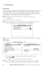
Page 37: ...ational mode until it receives an input Please refer to local regulations for use of this input The panel is supplied in an operational state 1 ENABLE input MX16 NX16 panel is provided with an input t...

Page 38: ...ceived unit MX Power connection PSU and Main Board In place in received unit MX AC Mains Input To be done by installer Refer to Figure 28 MX PSU Battery To be done by installer Wire harness provided R...

Page 39: ...9 2011 standard 11 1 Wiring check Cable readings should be recorded Consult local regulations On completion of the wiring or sections of the wiring the installer should carry out tests to ensure the i...

Page 40: ...s are on Refer Figure 43 a AC Power b Power c System Health ote N The system will not power on directly from the battery In the event of mains failure the system will shift to battery power to continu...

Page 41: ...Use Back button to move one step back one screen up Use Up and Down button to navigate through menu screen Pressing Up button at the top of a menu will take you to the last menu option For Menu optio...

Page 42: ...EER 2 to configure the system To login perform below steps 1 Press any key ACCEPT UP DOWN 2 Select ENGINEER 2 profile to log in 3 Enter the 4 digit pin required Default PIN 9999 ote N As an enhanced s...

Page 43: ...ul operation ote N New PIN needs to be different from last used 5 PINS for the user In case of any error press Back until all input values are cleared and enter the value again ote N User login and PI...

Page 44: ...will give a confirmation message if input is saved 5 Press Back to go back up one menu ote N User will not be able to enter incorrect values ENGINEER 2 7 Manage Users 8 Display Settings 9 SystemTime...

Page 45: ...g 2 Choose relevant DST settings as per location Press Accept 3 Option for DST are Off default New Zealand Australia North America Europe UK ote N Event log Set date and Set time are stored in event l...

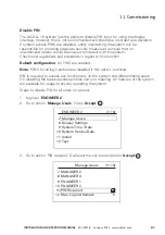
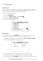
Page 46: ...ng will allow panel to act on the input If this behavior is not desired then de select the checkbox 4 Press Back ENGINEER 2 7 Manage Users 8 Display Settings 9 SystemTime Date 10 System Service Date 1...

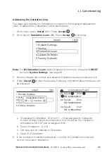
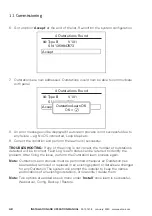
Page 47: ...ssigned to Outstation in order of their connection and position from the panel The Outstation connected to OS OUT port is assigned ID 1 b Type of Outstation A or B c Software version installed on Outs...

Page 48: ...er of outstations detected will be incorrect Fault Log Learn status can be referred to identify the problem After fixing the issue perform the Outstation learn process again ote N Outstation Learn pro...

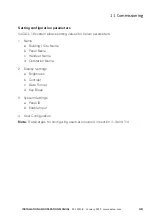
Page 49: ...system allows setting values for below parameters 1 Name a Building Site Name b Panel Name c Handset Name d Outstation Name 2 Display Settings a Brightness b Contrast c Date Format d Key Bleep 3 Syste...

Page 50: ...pe B Outstation installed at staircase of 2nd floor Panel name could be name of building panel is installed in Handset name could be the location in building where panel is installed ote N Update the...

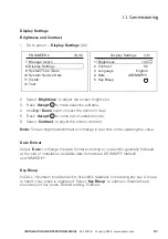
Page 51: ...te format according to convention generally followed at the site of installation Available date formats are DD MM YY default and MM DD YY Key Bleep VoCALL 16 system provides facility of audible feedba...

Page 52: ...on this input only if it is activated under install system settings menu Default settings of system is disabled ote N Any active call on the network is not impacted by application the input signal Ser...

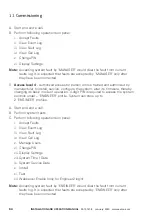
Page 53: ...em controls under USER profile System can store up to 5 USER profiles Default functionality available for USER profile A Start and end a call to give assistance to a member of the public B Perform fol...

Page 54: ...urer to install service configure the system alter its firmware thereby changing its basic mode of operation 4 digit PIN is required to access the system controls under ENGINEER profile System can sto...

Page 55: ...CALL16 system allows flexibility for changing the default functions available to each access profile individually System can be configured to provide more or less functionality than enabled by default...

Page 56: ...nabled 6 The profile enabled will have default rights as described in Section 11 3 Manage Users MANAGER 2 MANAGER 3 ENGINEER 1 ENGINEER 2 PIN Required Max Login Attempts 10 13 7 8 9 10 11 12 5 ENGINEE...

Page 57: ...event log of the panel 4 Fault log Permission to view fault log of the panel 5 Call log Permission to view call log of the panel 6 Manage Users Permission to enable modify access rights and PIN for a...

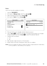
Page 58: ...tures that are accessible to the profile ENGINEER 2 7 Manage Users 8 Display Settings 9 SystemTime Date 10 System Service Date 11 Install 12 Test 7 13 MANAGER 1 1 Change PIN 2 Name 3 Access Rights 4 E...

Page 59: ...er length allowed is of 16 characters 9 Default names would be considered if names are not updated ote N Ensure to change the name to reflect the name of person position responsible for the operation...

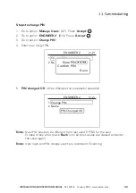
Page 60: ...ation email message A user of the system can also change its own PIN later if it is provided with required permission Steps to change PIN for own profile 1 Login to access profile 2 Go to option Chang...

Page 61: ...NS for all login profiles are disabled if this option is utilized PIN is required to access any functionality on the system and differentiating users On disabling the feature access profiles carry no...

Page 62: ...In the situation where the ENGINEER 2 access profile PIN number has been forgotten or lost the PIN can be recovered by using below steps 1 Press the LCD navigation keys simultaneously BACK UP DOWN ACC...

Page 63: ...system configuration to an earlier state This can help in saving installation time when any device panel or outstation is replaced Steps to restore settings from an earlier stored config file 1 Login...

Page 64: ...aved ote N Do system outstation learn operation post restoring the configuration file Parameters saved in configuration file 1 System Settings a Panel parameters i ID ii Type main network panel iii Se...

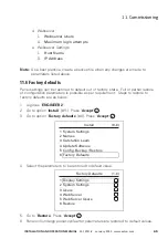
Page 65: ...in as ENGINEER 2 2 Go to option Install 11 Press Accept 3 Go to option Factory defaults 6 Press Accept 4 Select the parameters to be restored to default value 5 Go to Restore Press Accept 6 Panel will...

Page 66: ...ates when the primary power supply is removed 11 8 Documentation On completion of the installation and commissioning it is necessary that adequate records and other documentation are provided to the p...

Page 67: ...Figure 40 Calling procedure outstation 12 2 Receiving the call on Outstation Type A outstations can receive the call by lifting the handset from the housing Type B outstations can receive the call by...

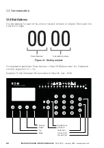
Page 68: ...o 2 parts of 2 digits Figure 41 Dialing number For standalone application Panel Number Panel ID Default value 01 Outstation number ranges from 01 16 Example To Call Outstation 5 connected to Panel 1 d...

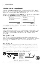
Page 69: ...6 Making a call from the panel handset Lift the handset on the control phone Dial the number of the outstation and press ACCEPT Call to call the line will connect automatically when the remote handset...

Page 70: ...cel or put the handset down to end the call 12 10 Speak only call Speak only call is unidirectional call with a type B Outstation It allows panel to transmit audio to a selected type B outstation Dial...

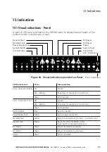
Page 71: ...station Figure 43 Visual indications provided on Panel LED Indications Color Interpretation CALL Indication Panel Off No Call Red blinking Out going In coming call Call on hold Green Call in progress...

Page 72: ...continuously until a Fault is corrected b Fault is acknowledged This would silence the buzzer Buzzer would replay fault tone after 8 hours if fault condition still exists 2 Call Indication Buzzer play...

Page 73: ...lt is acknowledged by user on the panel Buzzer would replay the fault tone after 8 hours if fault still exists 2 Call Indication a Buzzer plays ring tone when there is an incoming call on Type A Outst...

Page 74: ...n are recorded On Hook OS Call has been disconnected by OS Off Hook OS Handset has been lifted Call button pressed Ringing Call has been initiated It is not yet received on the other end OS MX Start C...

Page 75: ...by Outstation Call Log 1 3 01 01 19 00 08 54 OS End Call 0103 1 01 01 19 00 08 30 OS Start Call 0103 2 01 01 19 00 08 30 Dial Number 0103 3 Call Log 1 4 01 01 19 00 08 54 Ringing 0103 4 Call Log 1 4 0...

Page 76: ...er 0103 4 Call Log 1 4 01 01 19 03 36 11 MX End Call 0101 1 01 01 19 03 35 59 Speak Only 0101 2 01 01 19 03 34 18 MX End Call 0101 3 Call Log 2 4 01 01 19 00 10 54 Hold Call 0102 2 01 01 19 00 10 30 O...

Page 77: ...is connected Battery Resistance Battery resistance has increased over time beyond limit and needs replacement In case of above faults check the power connections AC mains to PSU PSU to main board PSU...

Page 78: ...el switch on type B OS is either not working or is jammed Off Hook Fault Panel or Type A OS handset is in off hook state for more than 90 seconds SD Card Not Present Error Error accessing SD Card on t...

Page 79: ...ion is enabled when jumper is connected on CON8 on main PCB Figure 44 MX16 Main PCB board CON8 position POWEER C NO C NO C NO MAIN BOARD ENABLE FAULT IN USE CRADLE JUMPER CON8 HANDSET 1 2 1 2 1 2 SDA...

Page 80: ...THERMISTOR IN USE C NO 2 1 FAULT C NO 2 1 ENABLE IN 0V 2 1 OS OUT PORT A 1 CANH 2 CANL 3 SHLD 4 SHLD 5 GND 6 24V OUTPUT NC NC 24V 0V 1 2 3 4 MAINS 1 LIVE 2 NEUTRAL 3 4 EARTH BATTERY 0V 24V T T 1 2 3 4...

Page 81: ...OCK DATA 1 2 3 4 A A D D C C B B G F E G F E T T T T 1 CANH 2 CANL 3 SHLD 4 SHLD 5 GND 6 24V OS IN PORT B 1 CANH 2 CANL 3 SHLD 4 SHLD 5 GND 6 24V OS OUT PORT A 1 CANH 2 CANL 3 SHLD 4 SHLD 5 GND 6 24V...

Page 82: ...OUT PORT 1 1 RX 2 RX 3 TX 4 TX 5 SHLD 6 SHLD ETHERNET PANEL IN PORT 2 1 RX 2 RX 3 TX 4 TX 5 SHLD 6 SHLD OUT 1 OUT 2 24V 0V 24V 0V 1 2 3 4 MAINS 1 LINE 2 NEUTRAL 3 4 EARTH BATTERY 0V 24V T T 1 2 3 4 CO...

Page 83: ...SHLD 6 SHLD ETHERNET PANEL IN PORT 2 1 RX 2 RX 3 TX 4 TX 5 SHLD 6 SHLD OUT 1 OUT 2 24V 0V 24V 0V 1 2 3 4 MAINS 1 LINE 2 NEUTRAL 3 4 EARTH BATTERY 0V 24V T T 1 2 3 4 COMMUNICATION NC NC CLOCK DATA 1 2...

Page 84: ...TX 5 SHLD 6 SHLD ETHERNET PANEL IN PORT 2 1 RX 2 RX 3 TX 4 TX 5 SHLD 6 SHLD OUT 1 OUT 2 24V 0V 24V 0V 1 2 3 4 MAINS 1 LINE 2 NEUTRAL 3 4 EARTH BATTERY 0V 24V T T 1 2 3 4 COMMUNICATION NC NC CLOCK DAT...

Page 85: ...TX 4 TX 5 SHLD 6 SHLD OUT 1 OUT 2 24V 0V 24V 0V 1 2 3 4 MAINS 1 LIVE 2 NEUTRAL 3 4 EARTH BATTERY 0V 24V T T 1 2 3 4 COMMUNICATION NC NC CLOCK DATA 1 2 3 4 A A D D C C B B G F E G F E T T T T HANDSET...

Page 86: ...CANL 3 SHLD 4 SHLD 5 GND 6 24V PANEL OUT PORT 1 1 RX 2 RX 3 TX 4 TX 5 SHLD 6 SHLD ETHERNET PANEL IN PORT 2 1 RX 2 RX 3 TX 4 TX 5 SHLD 6 SHLD OUT 1 OUT 2 24V 0V 24V 0V 1 2 3 4 MAINS 1 LINE 2 NEUTRAL 3...

Page 87: ...s updated from default values DISPLAY SETTINGS SET Display settings updated from default values USER PIN CHANGED Change in PIN of any USER USER SETTING CHANGED Change in settings of any USER WEBSERVER...

Page 88: ...n place OS HANDSET OFF HOOK Handset on outstation kept in off hook state for more than 90 secs in absence of active call MX HANDSET OFF HOOK Handset on panel kept in off hook state for more than 90 se...

Page 89: ...lder on SD Card The files would have aes extension 4 Safely eject the SD Card Plug the SD Card back in socket provided 5 Close the top cover Power up the panel 6 Login as Engineer 2 7 Go to menu optio...

Page 90: ...ndividual is expected to have been trained on system usage and maintenance by the manufacturer or installer of the system The responsibilities include but are not limited to below 1 Ensuring maintenan...

Page 91: ...and visual indicators at the panel should be checked for correct operation 5 All fault indicators should be checked where practicable by simulation of fault conditions Following modules can be self t...

Page 92: ...el Location Root UPDATES EVCS Log Viewer 1 Below files available on SD card are needed for viewing the logs a Configuration file b Respective log file 2 Ensure use of updated Configuration file and lo...

Page 93: ...on to read log files 5 Separate tabs are provided to read relevant log file Ensure correct tab is used to open the file 6 Application allows multiple log files from the same system to be accessed Logs...

Page 94: ...llation and operation manual 25 13741 E January 2020 www eaton com 17 Log Viewer 9 Logs can be exported from the application and saved on PC as a text file excel file To save the logs click on Save Lo...

Page 95: ...arious filter can be applied on data a Sorting of data in ascending descending order as per column Click on column header and select the order b Entry number Select entry numbers required Apply c Date...

Page 96: ...96 Installation and operation manual 25 13741 E January 2020 www eaton com 17 Log Viewer...

Page 97: ...18 1 Connect to Webserver Webserver is configured to work with Static IP address on a peer to peer connection between PC and MX16 panel Settings required on PC Laptop for Windows 10 PC 1 Go to Network...

Page 98: ...panel ethernet port Webserver is provided with fixed IP address 192 168 1 17 DHCP is not supported 7 Login in to panel via LCD as ENGINEER 2 Go to option Web Server 13 Select the tick box 8 Open web b...

Page 99: ...default login details User name password after first login using change password option 11 After successful login below landing page will be visible The screen shows an overview of the system health...

Page 100: ...ystem All webpages are divided into three parts 1 Top pane 2 Navigation pane on left 3 Sub page a Navigation b Information Top pane 1 Webserver software version 2 Language selection English language i...

Page 101: ...ration parameters details of all the devices 4 Manage Users Access rights user parameters for Webserver users ote N Webserver user details and parameters are limited to access of Webserver only They a...

Page 102: ...information is displayed for a particular panel selected depicted by the drop down option at top of the page To access information of another panel select another panel from the drop down menu Logs Th...

Page 103: ...103 Installation and operation manual 25 13741 E January 2020 www eaton com 18 Webserver...

Page 104: ...hen accessing Install page Webserver will put system in Engineering Mode In this mode no calls will be allowed on the system Access of Install sub menus on LCD will also be prohibited Navigating to an...

Page 105: ...station Name d Handset Name 2 Enable Input settings ote N Route Calls section is not relevant for standalone installation Manage Webserver Users Webserver allows up to 10 user profiles to be configure...

Page 106: ...eaton com 18 Webserver Webserver can be used for real time status monitoring of the panel Figure 54 OS 02 calling panel Figure 55 Call to OS 02 kept on hold Figure 56 Listen in call from OS 15 Figure...

Page 107: ...hecklist MX 16 Panel 1 Display Unit 2 Main PCB 3 Power Supply Unit 4 Handset 5 Accessories Pouch a Battery connection wire harness b Key 6 Installation Leaflet 7 Connectors Type A Outstation 1 Main PC...

Page 108: ...nged while configuring the system ote N Only activate the access profiles desired during the configuration of the system APPENDIX 3 SD Card contents Root Folder Folder File Name Content Revision txt S...

Page 109: ...iving a Call Lift the handset If more than one line is calling all calling lines will show in the display and can be scrolled through with the navigation buttons and selected Engineering assistance Fi...

Page 110: ...details Outstation Outstation Type Outstation Name Outstation Location Serial Number Dial Number 01 0101 02 0102 03 0103 04 0104 05 0105 06 0106 07 0107 08 0108 09 0109 10 0110 11 0111 12 0112 13 0113...

Page 111: ...per local standard and guidelines or as per instructions provided in the manual Any deviation is recorded A Products are mounted in appropriate location and at appropriate height A All units have bee...

Page 112: ...Test Panel Information Manage Users Display Settings Install Test Enable Web Server USER 1 USER 2 USER 3 USER 4 USER 5 MANAGER 1 MANAGER 2 MANAGER 3 ENGINEER 1 Brightness Contrast Language Date Syste...

Page 113: ...in an asset inventory that uniquely identifies each important component To facilitate this VoCALL 16 supports the following identifying information manufacturer type serial number Firmware version num...

Page 114: ...leges should be assigned only to accounts specifically designated for administrative duties and not for regular use Leverage the roles access privileges mentioned in Section 11 to provide tiered acces...

Page 115: ...115 Installation and operation manual 25 13741 E January 2020 www eaton com Notes...

Page 116: ...ters Route de la Longeraie 7 1110 Morges Switzerland Eaton eu 2020 Eaton All Rights Reserved Publication No 25 13741 E January 2020 Eaton is a registered trademark All trademarks are property of their...

Reviews: