21
InStALLAtIon And opErAtIon mAnuAL
25-13741-E
January 2020 www.eaton.com
10. Installation
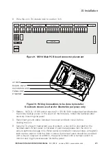
6. Wire the unit. For details refer to section 10.5
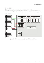
Figure 9. mX16 main pCB board connector placement
Figure 10. Wiring Connections to be done by installer.
Knockouts shown used are for illustration purposes only.
7. Battery: VoCALL 16 MX panel requires 2 x 12V @ 12Ah sealed lead acid batteries
to provide backup power in the event of mains failure. Install the batteries after
securely mounting the panel.
8. Reconnect ground cable, between top cover and back cover, before
closing the unit.
9. Security: To prevent inadvertent use of system, a key lock is provided for the
handset cabin. When panel is installed in public area please lock the door to
ensure authorized usage only. When panel is installed in secured area, a magnetic
latch can be used to hold the door in place. Authorized users should be provided
with a key as required. In addition, the panel is fitted with a tamper switch to
monitor and log physical access inside the panel.
POWEER
C
NO
C
NO
C
NO
MAIN BOARD
ENABLE
FAULT
IN USE
CRADLE
JUMPER
CON8
HANDSET
1
2
1
2
1
2
SDA
4
SCL
3
GND
2
V
1
CANH
DISPL
AY
UNIT
1
2
3
4
5
6
CANL
SHL
D
SHL
D
GND
24V
CANH
PANEL IN (PORT 2)
ETHERNET
PANEL OUT (PORT1)
OS IN (PORT B)
OS OUT (PORT A)
1
2
3
4
5
6
CANL
SHL
D
SHL
D
GND
24V
RX+
1
2
3
4
5
6
RX-
TX+
TX-
SHL
D
SHL
D
RX+
1
2
3
4
5
6
RX-
TX+
TX-
SHL
D
SHL
D
AC MAIN
RELAYS / INPUT
OUTSTATION LOOP
ETHERNET
PANEL LOOP
Summary of Contents for VoCALL 16
Page 96: ...96 Installation and operation manual 25 13741 E January 2020 www eaton com 17 Log Viewer...
Page 103: ...103 Installation and operation manual 25 13741 E January 2020 www eaton com 18 Webserver...
Page 115: ...115 Installation and operation manual 25 13741 E January 2020 www eaton com Notes...


