INSTALLATION
EATON
Powerware
®
BladeUPS
®
(12 kVA) User's Guide
S
164201649 Rev 3
www.powerware.com
49
Load
Connector
Breaker
Input
Breaker
Battery
Breaker
Load
Connector
REPO (NC)
REPO (NO)
Communication Port
Ground
Bonding
Screw
Extended
Battery
Connector
X-Slot Communication Bay 1
X-Slot Communication Bay 2
Output Power Cord
Input Power Cord
Surge
Protection
(leave
installed)
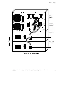
Figure 32. BladeUPS Rear Panel (Standalone UPS Shown with IEC 309-60A Output Power Cord)
NOTE
The load connector breaker controls the load connector only, not the output power
cord.

