


Page
2-2
www.eaton.com
IB02602002E
MP-4000
2.1.9 Under and Over Voltage Protection
The MP 4000 has under (27) and over (59) voltage protection. Under
and over voltage protection have separate start delays to prevent
nuisance tripping during startup. Separate alarm functions are also
provided.
2.1.10 Under Power Protection
The MP 4000 has under power (32) protection. Trip, start and run tim
-
ers, and a separate alarm threshold setting are provided.
2.1.11 Power Factor
The MP-4000 has power factor (55) protection. Separate setpoints are
provided for leading and lagging power factors. For both leading and
lagging power factors, threshold settings are provided. The start and
run timers are shared by both leading and lagging, while the threshold
settings are distinct. A separate alarm threshold setting is provided.
2.2 Motor Starting and Control Functions
The MP-4000 Motor Protection Relay includes logic to control the num
-
ber of starts that can occur on the motor in a given time period for cold
and hot motor conditions. Settable timers are provided to control the
time between starts and to restart a motor after a stop. Additional logic
is included for transition control of reduced-voltage starters.
2.2.1 Start Control Timers
Motors typically have limits on the number of cold starts, starts per time
period, and time between starts that are permitted without damage.
The MP-4000 incorporates these checks to prevent excessive starting
of the motor.
2.2.2 Reduced Voltage Starting
The MP-4000 provides transition and incomplete sequence detection
function for reduced voltage starting. The User can select to transi
-
tion based on four logical combinations of starting current and time
sequence. The incomplete sequence function can be used indepen
-
dently for feedback indication from the process to trip the motor if
expected action does not occur.
2.2.3 anti-backspin Timing
For certain applications, such as pumping a fluid up a pipe, the motor
may be driven backward for a period of time after it stops. The MP-
4000 provides an anti-backspin timer (minimum time between stop and
restart) to prevent starting the motor while it is spinning in the reverse
direction. The relay displays the timer countdown from the moment a
stop is declared by the relay.
2.2.4 load Shedding
The MP-4000 provides a mechanical load shedding feature that can be
used to control the driven process. The load shedding function closes
a contact on an overload condition to stop addition of load until the
overload condition subsides by a set amount. Then the load shedding
contact opens and the load is restored.
2.2.5 Emergency Override
The MP-4000 has a User-programmable feature that lets the operator
reset certain trip conditions, including the jogging timers and thermal-
model overload bucket. This function is for use in emergency condi
-
tions only and may result in motor damage or failure. The override
action is logged with time-tag. The pushbutton is located behind a
security door. The function can be disabled.
2.2.6 long acceleration Motors
Large motors with high inertia loads, such as centrifuges and large
fans, may experience starting currents that greatly exceed the full
load current for greater than the locked rotor time. The MP-4000 has
a timing feature that holds off thermal tripping during the long accel
-
eration. This should be used with a zero speed switch input.
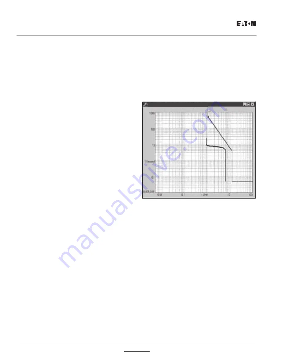
2.2.7 Motor Starting Profile
The MP-4000 records the average current and voltage versus time for
the last four starting cycles. This information is available via the com
-
munications port. The PowerNet host plots the motor current versus
the motor cold-start protection curve, as shown in Figure 2.1.
2.3 User Interface
The MP-4000 Motor Protection Relay has a User-friendly interface
that makes it easy to retrieve important information or to make set-
ting changes. LEDs provide visual indication of display mode. The
pushbutton access scheme is easy to learn, and quickly accesses the
large volumes of setting, monitoring, logging, and historical informa
-
tion.
The User may also access settings via the front panel RS-232 port.
The JTAG port is for factory use only.
Figure 2.1 Motor Starting Profile
-
ber of starts that can occur on the motor in a given time period for cold
Additional logic
Motors typically have limits to the number of cold starts, starts per time
The
Fig. 2.1 Motor Starting Pro
fi
le
MP-4000 Protection and Motor Start Curves
Summary of Contents for MP-4000
Page 6: ...Page vi www eaton com IB02602002E MP 4000 This Page Intentionally Left Blank...
Page 56: ...Page 5 16 www eaton com IB02602002E MP 4000 This page intentionally left blank...
Page 60: ...Page 6 www eaton com IB02602002E MP 4000 Figure 6 2 Panel Cutout Dimensions...
Page 64: ...Page 6 www eaton com IB02602002E MP 4000 Figure 6 6 Rear Panel Terminals...
Page 67: ...www eaton com Page 6 11 MP 4000 IB02602002E Figure 6 11 Alternatives for Discrete Input Wiring...
Page 72: ...Page 7 www eaton com IB02602002E MP 4000 This Page Intentionally Left Blank...
Page 83: ...www eaton com Page 9 MP 4000 IB02602002E Figure 9 1 Rotor Temperature Tracking...
Page 84: ...Page 9 www eaton com IB02602002E MP 4000 Figure 9 2 Motor Protection Curve...
Page 85: ...www eaton com Page 9 MP 4000 IB02602002E Figure 9 3 Underload Jam Protection Curve...
Page 88: ...Page 9 12 www eaton com IB02602002E MP 4000 Figure 9 6 Motor Start and Run Cycles...
Page 110: ...Page 13 10 www eaton com MP 4000 IB02602002E This Page Intentionally Left Blank...
Page 111: ...www eaton com MP 4000 IB02602002E This Page Intentionally Left Blank...


