


Introduction
Eaton ePDU G3 Operation Manual P-164000277—Rev 1
www.eaton.com/ePDU
4
LCD Interface
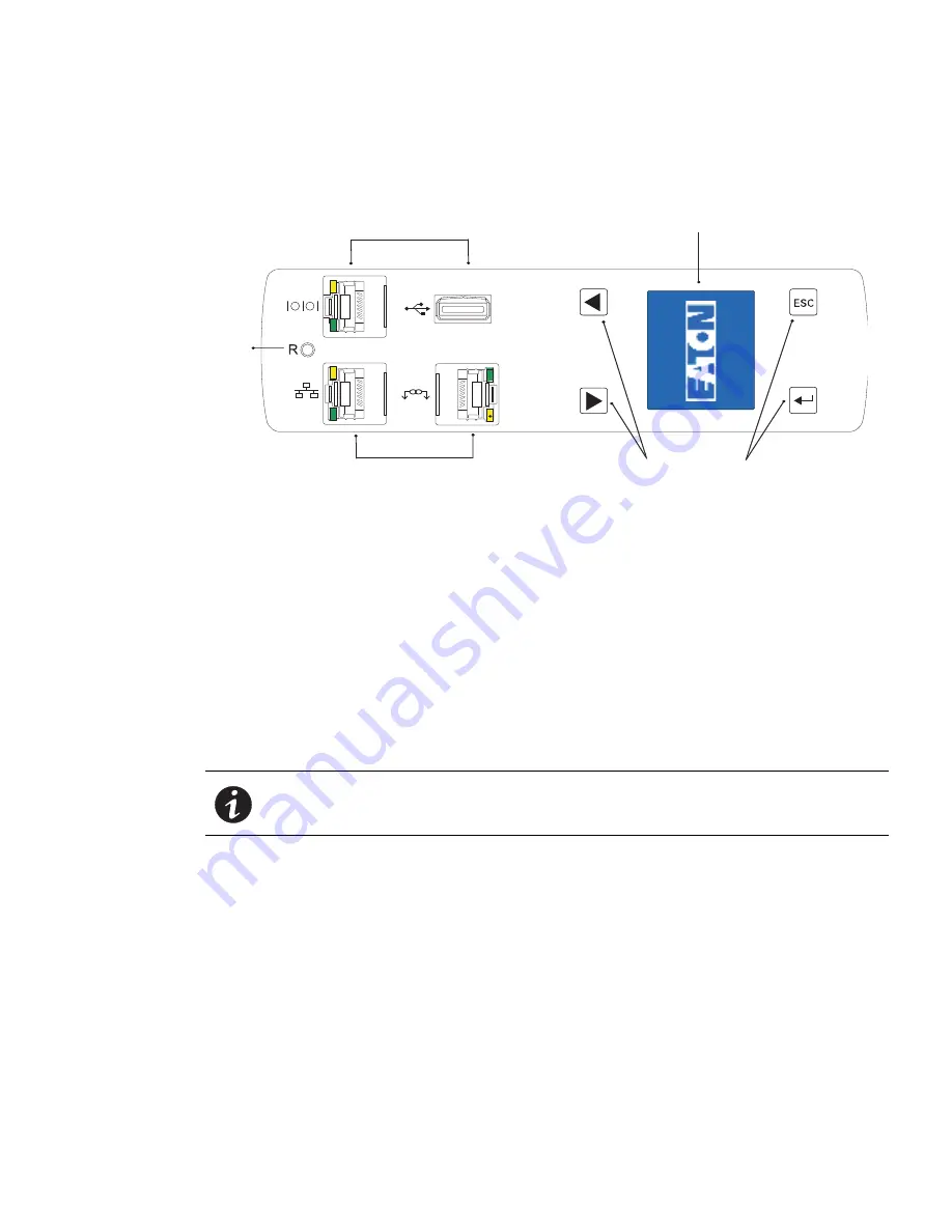
The LCD interface is operated using the LCD display, buttons, and ports of the embedded communications
module (ePDU Network Management and Control (eNMC) module). See Figure 3.
Reset
Button
Serial Port and USB Port
Ethernet Port and Daisy Chain Port
LCD Display
Navigation Buttons
Figure 3. LCD Interface Front Panel
LCD Display
The LCD display provides information about load status, events, measurements, identification, and settings.
The LCD interface also provides some basic configuration. For more information, see “Operation Interfaces”
on page 28.
Navigation Buttons
Navigate through the display with buttons. For more information, see “Ports, Operation Buttons and LED Status
Indicators” on page 30
Reset Button
Restart (reset) the ePDU Network Management and Control (eNMC) module through this button. Insert and
retract a probe in the reset button opening to perform a communications module restart.
NOTE
Resetting the ePDU does not affect the power to the outlets.
Connectivity and Serial Ports
l
Serial or Environmental Monitoring Probe (EMP) Port.
Connects to the serial (COM) RS-232 connector
on a computer with a DB9-to-RJ-45 cable, allowing the computer to act as a configuration console. As an
alternative, the connection can be used to connect an optional EMP in order to collect temperature and
humidity data.
l
Ethernet Port Connector.
Connects to a LAN, allowing configuration through a 10/100 autosensing network
connection.
l
Daisy Chain Port Connector.
Used to daisy-chain two to four ePDUs together to use a single Ethernet
connection.
l
USB Port.
Used for firmware upgrade.


