3 Installation
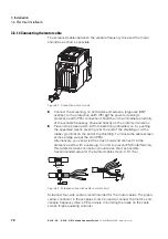
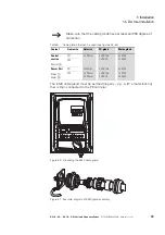
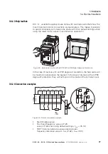
3.6 Electrical Installation
DC1-S…20…, DC1-S…OE1 Variable Frequency Drives
05/21 MN040058EN
www.eaton.com
79
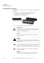
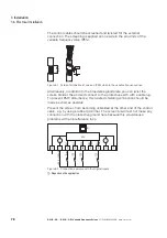
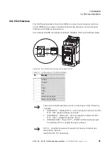
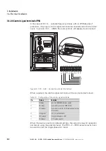
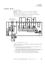
Connection terminals
Description
Factory Set
The digital inputs are driven with the internal control voltage from
terminal 1 (+24 V).
Frequency reference value via the analog input using an external
potentiometer and the internal control voltage from terminal 5
(+10 V).
External control and reference voltages
Digital inputs DI1 and DI3 are driven with an external control
voltage (+24 V).
The setpoint value (REF) is set with an external analog voltage
(0 -+10 V) via control signal terminal 6 (AI1).
Hint:
The two external voltage sources are connected to each other via
the common reference potential (0 V) (control signal terminals 7
and 9).
External control voltage through PLC
Digital inputs DI1 and DI3 are driven by digital PLC outputs (+24 V
external control voltage).
The setpoint value (REF) is set by an analog PLC output (reference
voltage of 0 -+10 V) via control signal terminal 6 (AI1).
Frequency actual value (f-Out, 0 -+10 V) from control signal
terminal 8 (AO1) to an analog PLC input.
Hint:
The two external voltage sources are connected to each other via
the common reference potential (0 V) (control signal terminals 7
and 9).
0...+10 V
Start
AI1
(DI4)
DI2
f-Fix1
DI3
DI1
6
4
3
2
1
X1
+10 V, < 10 mA
+24 V, < 100 mA
AO1
(DO1)
0 V
7
5
REF
9
8
CPU
0...+10 V
Start
AI1
(DI4)
DI2
f-Fix1
DI3
DI1
6
4
3
2
1
X1
AO1
(DO1)
0 V
7
5
REF
9
8
CPU
A
D
+24 V
REF
f-Out
Start
AI1
(DI4)
DI2
f-Fix1
DI3
DI1
6
4
3
2
1
X1
AO1
(DO1)
7
5
9
8
0 V
+24 V
0 V
CPU
A
D
A
D
Summary of Contents for DC1-S1011NB-A20CE1 1
Page 4: ......


