5 Operation
5.6 Commissioning with local controls
116
DC1-S…20…, DC1-S…OE1 Variable Frequency Drives
05/21 MN040058EN
www.eaton.com
5.6 Commissioning with local controls
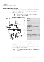
DC1-…-A6S… variable frequency drives with local controls are configured
and wired at the factory. They can be started directly using the local controls
when the rated motor output for the mains voltage is connected (see the
connecting example below).
Simplified connecting example
When the specified supply voltage is applied at the mains connection
terminals (L1/L, L2/N) and the main switch (PWR
③
) on the mains side is
switched on, the switched-mode power supply unit (SMPS) in the DC link
will be used to generate the control voltage and the 7-segment LED display
will light up (
StoP
).
At this point, the variable frequency drive will be ready for operation (correct
operating status) and in Stop mode. The start enable signal can then be
issued by with a start command (FWD).
→
Make sure that the switches
②
und
③
are open before
switching on the mains voltage.
DC1-S…-A6SN
Pin
Designation
PWR
Power
③
L1/L
Single-phase mains connection
L2/N
L3
–
Ground connection
1
Control v24 V (output, maximum 100 mA)
2
Start enable
3
Quick Stop
U
Connection for three-phase ac motor
(three-phase motor)
V
CO
5
Reference v10 V (Output, maximum 10 mA)
6
Frequency reference value f-Set (Input 0 – +10 V)
①
7
Reference potential (0 V)
6
7
5
1
2
3
0...+10 V
0 V
+10 V
f-Soll
①
+24 V
START
Quick Stop
L1/L
REV
OFF
FWD
L2/N
PWR
③
②
L
N
L1
L2
PE
PE
V
U
M
3 ~
→
Summary of Contents for DC1-S1011NB-A20CE1 1
Page 4: ......

