6 Parameter structure
6.4 Control signal terminals
124
DC1-S…20…, DC1-S…OE1 Variable Frequency Drives
05/21 MN040058EN
www.eaton.com
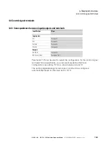
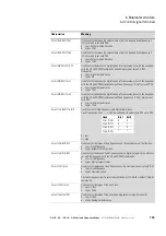
The following abbreviations are used throughout this document:
Table 32: Abbreviations
Abbreviation
Meaning
AI1 REF
Analog input AI1 (terminal 6)
Used as a speed setpoint input.
• P-16: configuration (voltage input, current input etc.)
• P-35: scaling
• P-39: offset
AI2 REF
Analog input AI2 (terminal 4)
Used as a speed setpoint input.
• P-47: configuration (voltage input, current input etc.)
DOWN
Used to reduce the speed if a digital setpoint value is selected (P-12 = 1 or = 2).
Used together with the UP command.
ENA
Variable frequency drive enable signal
A start signal (START, FWD, REV) is additionally required for starting. If ENA is
removed, the drive will coast.
EXTFLT
External Fault
Can be used to integrate an external signal into the variable frequency drive’s
fault messages. During operation, there must be a high-level signal at the
terminal. If the unit detects a low-level signal instead, the drive will be switched
off and display "
E-trip
" as a fault message.
PI feedback
PI controller process value signal
Pulse Start (NO)
Pulse STOP (NC)
Pulse control
Used to control the drive like with a latching contactor circuit. The Pulse STOP
signal must always be present when operating the drive. If the signal is not
present, it will not be possible to start the drive / the drive will ramp down to zero.
To start, all that is required is a pulse via the START signal.
The FWD and REV signals do not need to be continuously applied during
operation.
Select AI1 REF/AI2 REF
Used to select between the analog setpoint values on AI1 (terminal 6) and AI2
(terminal 4)
• AI1 = Low
• AI2 = High
Select AI1 REF/f-Fix
Used to select between the analog speed reference value at analog input 1
(AI1 = terminal 6) and a fixed frequency. The fixed frequency itself is selected
with the Select f-Fix Bit0, Select f-Fix Bit1, Select f-Fix Bit2 commands.
• Low = Analog setpoint value
• High = fixed frequency
Select AI1 REF/f-Fix1
Used to select between the analog speed reference value at analog input 1
(AI1 = terminal 6) and the fixed frequency 1 (f-Fix1) set with P-20.
• Low = Analog setpoint value
• High = f-Fix1
Select AI1 REF/f-Fix2
Used to select between the analog speed reference value at analog input 1
(AI1 = terminal 6) and the fixed frequency (f-Fix2) set with P-21.
• Low = Analog setpoint value
• High = f-Fix2
Select BUS REF/AI1 REF
Used to select between setpoint values
• Low = Setpoint value from bus
• High = AI1
Select BUS REF/DIG REF
Used to select between setpoint values
• Low = Setpoint value from bus
• High = fixed frequency
The fixed frequency itself is selected with the Select f-Fix Bit0, Select f-Fix Bit1
commands.
Summary of Contents for DC1-S1011NB-A20CE1 1
Page 4: ......


