6 Parameter structure
6.4 Control signal terminals
136
DC1-S…20…, DC1-S…OE1 Variable Frequency Drives
05/21 MN040058EN
www.eaton.com
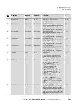
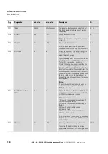
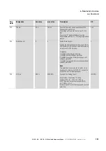
6.4.2.10 P-12 = 10: SWD control
Table 42: P-12 = 10: SWD control
P-15
DI1
(terminal 2)
DI2
(terminal 3)
DI3/AI2
(terminal 4)
DI4/AI1
(terminal 6)
0
START
No function
Select AI1 REF/f-Fix1
AI1 REF
1
START
Select AI1 REF/f-Fix
Select f-Fix Bit0
AI1 REF
2
START
Select f-Fix Bit0
Select f-Fix Bit1
Select f-Fix/f-max
3
START
Select AI1 REF/f-Fix1
EXTFLT
AI1 REF
4
START
Select AI2 REF/AI1 REF
AI2 REF
AI1 REF
5
Not permissible
6
FWD
No function
EXTFLT
AI1 REF
7
Not permissible
8
START
No function
Select f-Fix Bit0
Select f-Fix Bit1
9
Not permissible
10
Not permissible
11
Not permissible
12
Not permissible
13
START
No function
EXTFLT
No function
14
Not permissible
15
1)
ENA
No function
Select Fire Mode/Normal OP
No function
16
2)
ENA
Select AI1/f-Fix2
Select Fire Mode/Normal OP
AI1 REF
17
ENA
Select f-Fix Bit0
Select Fire Mode/Normal OP
Select f-Fix Bit1
1) If P-15 = 15 and fire mode is active, the drive will run with fixed frequency 4 (f-Fix4), which is set with P-13.
2) If P-15 = 16, the setpoint value selection will be independent from fire mode.
Summary of Contents for DC1-S1011NB-A20CE1 1
Page 4: ......


