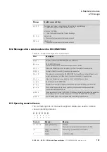
6 Parameter structure
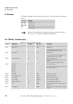
6.6 Parameter
152
DC1-S…20…, DC1-S…OE1 Variable Frequency Drives
05/21 MN040058EN
www.eaton.com
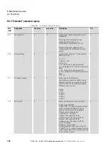
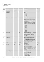
P-36
RS485-0 Address
1
63
1
RS485-0 Baudrate
0
6
Baud Rate
2: 9.6 kbit/s
3: 19.2 kBit/s
4: 38.4 kBit/s
5: 57.6 kBit/s
6: 115.2 kBit/s
6
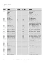
Modbus RTU0 COM Timeout
0
8
Modbus RTU0 COM Timeout
Time between a communication loss and the
resulting action.
Setting "0” disables the action after
communications trip.
t: indicates the drive will trip if time exceeded.
r: indicates the drive will ramp to stop if time
exceeded.
0: no action
1: t 30 ms
2: t 100 ms
3: t 1000 ms
4: t 3000 ms
5: r 30 ms
6: r 100 ms
7: r 1000 ms
8: r 3000 ms
4
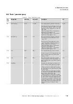
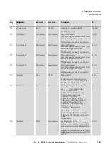
P-37
Password Level2
0
9999
Defines the password which is used to get access
to extended parameter set (Level 2).
In addition, it also defines the password needed to
get access to the advanced parameter set
(P-37 + 100).
Access via P-14.
101
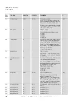
P-38
Parameter Lock
0
1
Determines whether to lock the parameters
0: OFF. All parameters can be changed.
1: ON. Parameter values can be displayed, but
cannot be changed. If a remote keypad is
connected, parameters cannot be accessed by the
remote keypad if they are locked.
0
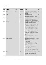
P-39
AI1 Offset
-500.00 %
500.00 %
Offset Analog Input 1
Resolution 0.1 %
0.00 %
P-40
Display Scale
0.000
16000 %
Scale factor display
Customer specific scaling factor.
With P-40 > 0 a “c” appears on the left hand side
of the display. With P-10 = 0 the scaling factor is
applied to the frequency, with P-10 > 0, to the
speed. The value is displayed in real-time on the
drives display.
0.000
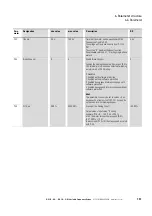
Display Scale Source
0
3
Source to Scale factor display
Source of the displayed value
0: Motor speed
1: Motor current
2: Analog Input AI2
3: PI controller feedback
0
Para-
meter
Designation
min. value
max. value
Description
DS
Summary of Contents for DC1-S1011NB-A20CE1 1
Page 4: ......


