4 Accessories
4.7 Device-specific accessories for devices with an IP20 degree of protection
98
DC1-S…20…, DC1-S…OE1 Variable Frequency Drives
05/21 MN040058EN
www.eaton.com
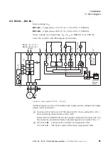
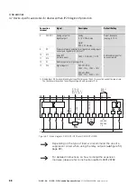
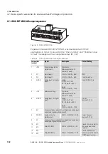
Figure 67: Block diagram DXC-EXT-IO110 and DXC-EXT-IO230
8
AO1/DO1
Analog output 1 or
digital output 1
analog:
0 - 10 V, 20 mA max.
digital:
0/24 V, 20 mA max.
Output Frequency
(analog, 0 - 10 V)
9
0 V
Common reference potential for all digital and analog inputs
and outputs together with terminal 7
–
10
K13
Relay RO1
(normally open)
250 V, 1 A AC/30 V, 1 A DC
RUN, enable signal for
device activated
11
K14
12
N
Reference point for digital input DI4
–
13
DI4
Digital Input 4
1)
DXC-EXT-IO110:
100 V - 10 % - 120 V + 10 %
DXC-EXT-IO230:
200 V - 10 % - 240 V + 10 %
–
1) Analog input AI1 (terminal 6) and digital input DI4 (terminals 12
and 13) cannot be used at the same time.
The function will depend on the settings configured with parameter P-15.
→
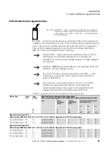
Depending on the type of load, we recommend the use of a
suppressor circuit when using the relay outputs (
→
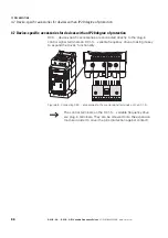
For detailed instructions on how to install the expansion
modules, please refer to instruction leaflet IL04012016Z.
Connection
terminal
Signal
Description
Default Setting
2
DI1
3
DI2
4
DI3
1
5
+10 V
< 20 mA
6
7
0 V
0 V
8
9
10
11
12
13
1
DC1
2
3
4
5
6
8
9
10
11
P-18 = 1
RUN
P-12 = 0
AI : P-15 = 5
DI4 : P-15 = 2
7
AI
0 ... +10 V
A0
0 ... +10 V/20 mA
N
DI4
N
f-Soll
f-Out
K1
250 V AC
220 V DC
1 A
4.7 kΩ
+
L
N
Summary of Contents for DC1-S1011NB-A20CE1 1
Page 4: ......


