6 Parameter structure
6.6 Parameter
DC1-S…20…, DC1-S…OE1 Variable Frequency Drives
05/21 MN040058EN
www.eaton.com
151
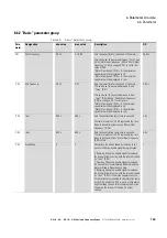
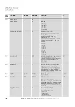
P-33
t-Boost
0.0 s
150.0 s
Time that the motor will be supplied with the
frequency defined in P-32.
The voltage will increase linearly from P-11 to
P-07.
The setting “0” disables the boost function.
See also
section 5.5.1, “Starting single-phase
5.0 s
P-34
Brake Chopper
0
4
Enable Brake Chopper
Enables the braking chopper on frame sizes FS2 to
FS4. Internal protection can be selected for braking
resistors with a 200 W rating.
0: Disabled
1: Enabled with software protection
2: Enabled without software protection
3: Enabled during speed reference change with
software protection
4: Enabled during speed reference change without
software protection
Hint:
This parameter can only be set to values > 0 on
devices with a frame size of FS2. FS1 devices do
not have an internal braking chopper.
0
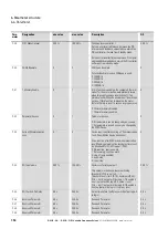
P-35
AI1 Gain
0.00 %
2000.00%
Scaling of the Analog Input 1
Output value = Input value * Scaling.
Example: P-16 = 0…10 V, P-35 = 200 %:
at 5 V the motor turns with max speed (P-01)
(5 V * 200 % = 10 V)
In slave mode (P-12 = 14) the slave speed is scaled
with P-35.
100.00 %
Para-
meter
Designation
min. value
max. value
Description
DS
Summary of Contents for DC1-S1011NB-A20CE1 1
Page 4: ......


