


ELECTRONIC SPEED CONTROL (48V)
Page F-25
Repair and Service Manual
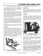
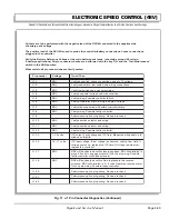
Read all of Section B and this section before attempting any procedure. Pay particular attention to all Notes, Cautions and Warnings
Fault
Code
Fault
Vehicle Operation
Change
Corrective Action
- - -
Direction Selector Fault Vehicle Operates in
One Direction Only
• At Direction Selector check wiring
Bad - Replace/repair wiring; Good - Replace selector switch
- - -
No Buzzer
Buzzer Inoperative
• Verify Run-Tow/Maintenance Switch is in ‘RUN’ position;
• Verify 48 volts at J1 Pin 10; Repair/replace Pin 10 wire;
• Verify 48 volts at J1 Pin 1; Repair/replace Logic Power;
• (In Reverse) Verify 48 volts at J1 Pin 2; Repair/replace wire or micro
switch in Direction Selector switch
0 - 0
No Fault Codes
Vehicle Inoperative
with Key ON
• Open Pedal Box, verify micro switch wiring is connected & is not dam-
aged; Repair/replace as necessary;
• Direction Selector Forward micro switch OPEN, verify switch is opera-
tional and wiring is connected & not damaged; Repair/replace as neces-
sary;
• Verify Key Switch is operational; Repair/replace as necessary
The following codes require the rear wheels be raised before performing tests:
1 - 1
Hardware Failsafe
Vehicle will not run
• Check motor wiring; Replace controller
1 - 2
Throttle Fault 1
Vehicle will not run
• Check pedal box adjustment, connections; Replace ITS
1 - 3
Speed Sensor Fault
Vehicle runs slowly
• Check speed sensor magnet, wire, sensor & connector connections;
Replace speed sensor if necessary
1 - 4
High pedal disable
Vehicle will not run
• Release and reapply pedal; Check pedal box, linkage, switch, key
switch
1 - 5
Motor stall
Vehicle stopped
• Remove mechanical blockage
2 - 1
Low Battery Voltage
Vehicle performance
reduced
• Perform discharge test; Charge batteries/replace bad batteries
2 - 2
High Battery Voltage
Vehicle performance
reduced
• Verify that battery system is less than 48 volts
2 - 3
Thermal Cutback
Vehicle performance
reduced
• Allow controller to cool and verify heat sink bolt tightness
2 - 4
Main driver on
Vehicle runs slowly
• Solenoid driver defective; Replace controller
2 - 5
Volts direct current fault Vehicle will not run
• Replace controller
3 - 1
Main driver off
Solenoid does not
close
• Replace controller
3 - 2
Solenoid Welded
Vehicle runs slowly
• Replace solenoid
3 - 3
Precharge fault
Vehicle will not run
• Check for additional electronics attached to B+; Replace controller
3 - 4
Field missing
Solenoid closes, Vehi-
cle will not run
• Check wiring; Replace power harness and motor if required
3 - 5
Field overcurrent
Vehicle will not run
• Field windings or power harness shorted; Verify; Replace motor if nec-
essary
Fig. 7 48 volt Fault Codes
Summary of Contents for MPT 800
Page 6: ...Page iv Repair and Service Manual TABLE OF CONTENTS Notes...
Page 10: ...Repair and Service Manual SAFETY INFORMATION Page viii Notes...
Page 12: ...GENERAL INFORMATION ROUTINE MAINTENANCE Page A ii Repair and Service Manual Notes...
Page 20: ...SAFETY Page B ii Repair and Service Manual Notes...
Page 32: ...BODY Page C ii Repair and Service Manual Notes...
Page 42: ...WHEELS AND TIRES Page D ii Repair and Service Manual Notes...
Page 46: ...FRONT SUSPENSION AND STEERING Page E ii Repair and Service Manual Notes...
Page 104: ...MOTOR Page G ii Repair and Service Manual Notes...
Page 112: ...BATTERIES AND CHARGING Page H ii Repair and Service Manual Notes...
Page 122: ...ELECTRICAL SYSTEM Page J ii Repair and Service Manual Notes...
Page 158: ...BATTERY CHARGER Page L ii Repair and Service Manual Notes...
Page 166: ...REAR SUSPENSION Page M ii Repair and Service Manual Notes...
Page 170: ...REAR AXLE Page N ii Repair and Service Manual Notes...
Page 176: ...WEATHER PROTECTION Page P ii Repair and Service Manual Notes...
Page 182: ...PAINT Page Q ii Repair and Service Manual Notes...
Page 186: ...TROUBLESHOOTING Page R ii Repair and Service Manual Notes...
Page 192: ...LIGHTNING PROTECTION AND GROUNDING Page S ii Repair and Service Manual Notes...
Page 198: ...GENERAL SPECIFICATIONS Page T ii Repair and Service Manual Notes...
Page 210: ...Page T 12 Repair and Service Manual GENERAL SPECIFICATIONS...


