


ELECTRONIC SPEED CONTROL (48V)
Page F-22
Repair and Service Manual
Read all of Section B and this section before attempting any procedure. Pay particular attention to all Notes, Cautions and Warnings
GENERAL TROUBLESHOOTING
Tool List
Qty. Required
Floor jack..................................................................... 1
Jack stands ................................................................. 2
Wheel chocks .............................................................. 4
Jumper wire (with alligator clips) ................................. 1
DVOM.......................................................................... 1
Socket, 3/8", 3/8" drive ................................................ 1
Ratchet, 3/8" drive ....................................................... 1
Torque wrench, in. lbs., 3/8" drive ............................... 1
Torque wrench, ft. lbs., 3/8" drive ................................ 1
Extension, 6", 3/8" drive .............................................. 1
Insulated wrench, 9/16" ............................................... 1
Wrench, 1/2"................................................................ 1
Wrench, 7/16".............................................................. 1
Phillips screwdriver, large ............................................ 1
Phillips screwdriver, small ........................................... 1
Shop towel................................................................... 1
Allen wrench, .050" ..................................................... 1
Drill bit, 7/32” ............................................................... 1
Symptoms
Vehicle does not operate, operates poorly or intermit-
tently.
Testing
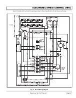
A maintenance feature of the 48 volt controller is the abil-
ity to diagnose electrical faults preventing the vehicle to
operate at its fullest potential. A light on the controller
face will blink informing the technician to the cause of the
vehicle malfunction.
A series of blinks will indicate the fault code (one, two,
three, four or five followed by a pause and one, two,
three, four or five more blinks). By reading the decal
attached near the controller, or by reading the 48 volt
Diagnostic Mode Fault Code chart (Ref Fig. 7 on page F-
25), the fault, its symptom(s) and corrective action to be
taken can be found.
It is unlikely that the mechanical adjustment of the pedal
box has changed, therefore the initial tests will be con-
ducted with a digital volt ohm meter (DVOM) to identify
the failed component.
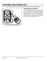
A typical DVOM is shown in illustrations. A recom-
mended DVOM is available through the E-Z-GO Service
Parts Department as P/N 27481-G01. Any DVOM may
be used; however, the accuracy, controls, displays and
features may vary depending on the make and model.
Always follow the meter manufacturer’s recommenda-
tions and instructions for the use and care of the meter.
To assure accurate readings, be sure to set the meter to
the closest voltage reading above the expected voltage.
To prevent injury result-
i ng f r om un ex pe ct ed
movement of the vehicle,
always raise the rear wheels before conducting any
tests.
To prevent possible motor damage, never operate
vehicle at full throttle for more than 4-5 seconds while
vehicle is in a “no-load” condition.
For static tests, raise the rear wheels of the vehicle and
support the vehicle on jack stands (Refer to the Lifting
Procedure in Section ‘B’ Safety). Test the vehicle stability
before proceeding.
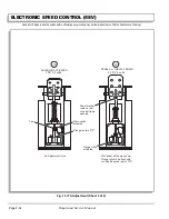
Place the direction selector in ‘F’ and turn the key switch
to ‘ON’. Depress the accelerator pedal until the micro
switch in the pedal box activates which should cause the
solenoid mounted to the controller to make an audible
click. If the solenoid does not click, test the batteries.
Testing Battery Voltage
It is important to determine the condition of the battery
set before proceeding with any electrical troubleshooting.
An open voltage test is of little use since a battery that
has deteriorated to the point of requiring replacement
can still show six volts or higher in an open voltage test. If
there is any doubt as to the adequacy of the battery set,
charge the batteries and perform a load test using a dis-
charge machine following manufacturer’s instructions. If
batteries are satisfactory, recharge battery set.
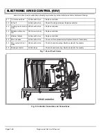
With the adequacy of the batteries confirmed, use a
DVOM connected directly to the battery terminal posts to
determine the open voltage of the set (Ref Fig. 4 on page
F-23). In the following tests, this voltage level will be
used as a reference. Some loss due to resistance of
wires and connectors may be indicated by readings that
could be up to one volt less than the reference voltage.
No reading indicates an “open” condition and the battery
wires should be inspected for a broken or disconnected
wire or component.
!
!
Summary of Contents for MPT 800
Page 6: ...Page iv Repair and Service Manual TABLE OF CONTENTS Notes...
Page 10: ...Repair and Service Manual SAFETY INFORMATION Page viii Notes...
Page 12: ...GENERAL INFORMATION ROUTINE MAINTENANCE Page A ii Repair and Service Manual Notes...
Page 20: ...SAFETY Page B ii Repair and Service Manual Notes...
Page 32: ...BODY Page C ii Repair and Service Manual Notes...
Page 42: ...WHEELS AND TIRES Page D ii Repair and Service Manual Notes...
Page 46: ...FRONT SUSPENSION AND STEERING Page E ii Repair and Service Manual Notes...
Page 104: ...MOTOR Page G ii Repair and Service Manual Notes...
Page 112: ...BATTERIES AND CHARGING Page H ii Repair and Service Manual Notes...
Page 122: ...ELECTRICAL SYSTEM Page J ii Repair and Service Manual Notes...
Page 158: ...BATTERY CHARGER Page L ii Repair and Service Manual Notes...
Page 166: ...REAR SUSPENSION Page M ii Repair and Service Manual Notes...
Page 170: ...REAR AXLE Page N ii Repair and Service Manual Notes...
Page 176: ...WEATHER PROTECTION Page P ii Repair and Service Manual Notes...
Page 182: ...PAINT Page Q ii Repair and Service Manual Notes...
Page 186: ...TROUBLESHOOTING Page R ii Repair and Service Manual Notes...
Page 192: ...LIGHTNING PROTECTION AND GROUNDING Page S ii Repair and Service Manual Notes...
Page 198: ...GENERAL SPECIFICATIONS Page T ii Repair and Service Manual Notes...
Page 210: ...Page T 12 Repair and Service Manual GENERAL SPECIFICATIONS...


