


ELECTRONIC SPEED CONTROL (48V)
Page F-21
Repair and Service Manual
Read all of Section B and this section before attempting any procedure. Pay particular attention to all Notes, Cautions and Warnings
The electrical power to the motor will be interrupted inter-
mittently allowing the vehicle to roll a short distance,
thereby allowing the internal components of the motor to
move before damage can be done.
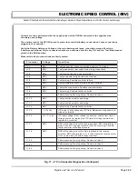
The No Plug option (See chart on page 1) features a dif-
ferent degree of compression breaking that takes place
any time that accelerator pedal is released. The No Plug
option will rapidly slow the vehicle to a stop unless the
accelerator pedal is depressed. The three other options
will slow the vehicle to a stop at different rates unless the
accelerator pedal is depressed.
The 48 volt system is a low power consumption unit but it
will drain the vehicle batteries over a period of time. If the
vehicle is to be stored for a prolonged period of time, the
48 volt system should be disconnected from the batteries
by selecting the ‘TOW/MAINTENANCE’ position on the
Run-Tow/Maintenance switch located under the passen-
ger seat.
The Electronic Speed Control system consists of three
separate units, a pedal box, speed sensor and controller.
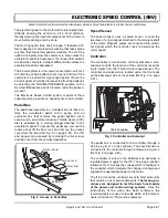
Pedal Box
The pedal box assembly is a modularized unit that con-
tains the accelerator pedal, return spring and an
enclosed box that contains the pedal position micro
switch and a solid state Inductive Throttle Sensor (ITS)
that is activated by a moving plunger attached to the
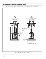
accelerator pedal. To access the pedal box, remove the
rocker panel, lift the floor mat, and remove the access
cover from the floor (Ref Fig. 2 on page F-21). The ITS
and plunger are accessed by removing the four screws
and top cover from the enclosed pedal box.
Speed Sensor
The speed sensor uses a sealed sensor to read the
impulses of a ring magnet attached to the armature shaft
of the motor. Magnetic pulses are converted into electri-
cal signals which the controller uses to determine the
motor speed.
Controller
The controller is a solid state unit that activates a sole-
noid and controls the function of the vehicle by respond-
ing to inputs from the ITS and motor speed sensor. The
controller and solenoid are located under the front seat
on the passenger side of the vehicle (Ref Fig. 3 on page
F-21).
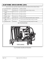
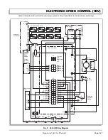
The pedal box is connected to the controller through a
24-pin plug at J1 on the controller. The speed sensor is
connected to the controller through a three-pin plug at J2
(Ref Fig. 8 on page F-26).
The controller is wired to the batteries and develops a
regulated power supply for the ITS. The plunger position
relative to the ITS varies the voltage which is fed back to
the controller which interprets the change in voltage and
supplies the appropriate power to the motor.
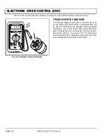
The ITS unit and the controller are both solid state units
that contain no user serviceable parts. The testing pro-
cedures are designed to test the basic functionality
of the power and control wiring systems. Once the
functionality of the wiring has been confirmed, the
remaining tests are used to identify which of the compo-
nents (controller or ITS) must be replaced.
Fig. 2 Access to Pedal Box
Rocker Panel
Floor Mat
Access Cover
Pedal Box
Fig. 3 Controller and Solenoid
J1
J2
J3
F1
F2
B+
B-
M-
1264 Controller
Summary of Contents for MPT 800
Page 6: ...Page iv Repair and Service Manual TABLE OF CONTENTS Notes...
Page 10: ...Repair and Service Manual SAFETY INFORMATION Page viii Notes...
Page 12: ...GENERAL INFORMATION ROUTINE MAINTENANCE Page A ii Repair and Service Manual Notes...
Page 20: ...SAFETY Page B ii Repair and Service Manual Notes...
Page 32: ...BODY Page C ii Repair and Service Manual Notes...
Page 42: ...WHEELS AND TIRES Page D ii Repair and Service Manual Notes...
Page 46: ...FRONT SUSPENSION AND STEERING Page E ii Repair and Service Manual Notes...
Page 104: ...MOTOR Page G ii Repair and Service Manual Notes...
Page 112: ...BATTERIES AND CHARGING Page H ii Repair and Service Manual Notes...
Page 122: ...ELECTRICAL SYSTEM Page J ii Repair and Service Manual Notes...
Page 158: ...BATTERY CHARGER Page L ii Repair and Service Manual Notes...
Page 166: ...REAR SUSPENSION Page M ii Repair and Service Manual Notes...
Page 170: ...REAR AXLE Page N ii Repair and Service Manual Notes...
Page 176: ...WEATHER PROTECTION Page P ii Repair and Service Manual Notes...
Page 182: ...PAINT Page Q ii Repair and Service Manual Notes...
Page 186: ...TROUBLESHOOTING Page R ii Repair and Service Manual Notes...
Page 192: ...LIGHTNING PROTECTION AND GROUNDING Page S ii Repair and Service Manual Notes...
Page 198: ...GENERAL SPECIFICATIONS Page T ii Repair and Service Manual Notes...
Page 210: ...Page T 12 Repair and Service Manual GENERAL SPECIFICATIONS...