


BRAKES - REAR MECHANICAL
Page K-12
Repair and Service Manual
Read all of Section B and this section before attempting any procedure. Pay particular attention to all Notes, Cautions and Warnings
Wheel Brake Inspection
Wear a dust mask and
eye protection whenever
w o r k i n g o n w h e e l
brakes. Do not use pressurized air to blow dust from
brake assemblies. Replace both brake shoes on both
wheels if one or more shoes are worn below .06”
(1.5mm) thickness at any point.
Do NOT touch any of the wheel brake
mechanism except as instructed.
Do NOT use a commercial brake cleaner unless the entire brake
has been disassembled.
1. Remove the brake drums.
Do not disturb adjuster mechanisms. Remove excess
dust and dirt from the drum with a brush.
The drum must not be
turned to “true” a worn
friction surface. Turning
will make the drum too thin causing drum failure and
a loss of brakes which could cause severe injury or
death.
2. Inspect the brake drum.
Look for a blue coloration or blistered paint that would
indicate that it has overheated. Check for evidence of
scoring. Check for excessive wear indicated by the
friction surface being significantly worn and leaving a
ledge of unworn drum. Inspect the splines for galling,
wear and corrosion. If any of these problems are
found, the drum must be replaced.
3. Remove any accumulated brake dust from the wheel
brake assembly with a brush.
4. Visually inspect the axle seal for oil leakage and the
condition of the thrust washer. If oil is present, see
REAR AXLE section.
5. Verify the inner brake drum washer is present and
check its condition. Replace if damaged or missing.
I f o n e w h e e l b r a k e
a s s e m b l y r e q u i r e s
replacement, the second
must also be replaced.
Use care when handling the adjuster
arm. Too much force will damage the
adjuster and require that both wheel brake assemblies be
replaced.
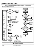
6. Visually check the condition and operation of the
adjuster mechanism.
Inspect the brake lever for damage or wear. Test the
adjuster function as follows:
Push the front brake shoe in the direction of the rear
of the vehicle and hold in position.
Operate the brake lever.
Observe the brake adjuster arm and note if the arm
engages the star wheel and attempts to rotate it (Ref
Fig. 15 on page K-12).
If the adjuster arm engages and turns the star
wheel, proceed. If the arm fails to engage the star
wheel, it has been damaged and both wheel brake
assemblies must be replaced.
If the adjuster arm engages the star wheel but fails to
rotate it, the adjuster assemblies must be replaced
with new color-coded adjusters. Note the location of
the two Teflon coated washers (Ref Fig. 22 on page
K-16).
7. Check the condition and operation of the moving
anchor assembly (Ref Fig. 22 on page K-16).
Operate the brake lever to check for free motion. The
adjuster assembly and brake lever should move
smoothly from front to back on the backing plate. If
the moving anchor assembly is damaged or binds
against the backing plate, replace both of the wheel
brake assemblies.
A backing plate assem-
bly that shows any indi-
c a t i o n o f g a l l i n g o r
gouging is not repairable and must be replaced with a
new wheel brake assembly. Always replace wheel
brake assemblies in pairs.
8. Inspect the backing plate.
Inspect for gouges, galling or other damage, particu-
larly where the backing plate is contacted by the
brake shoes and by the moving anchor assembly.
Replace both backing plates if any gouges or galling
is found.
!
!
!
!
!
!
Fig. 15 Adjuster Mechanism
Brake Adjuster
Arm
Star
Wheel
Adjusting
Screw
Front of Vehicle
Wheel Brake
Lever
!
!
Summary of Contents for MPT 800
Page 6: ...Page iv Repair and Service Manual TABLE OF CONTENTS Notes...
Page 10: ...Repair and Service Manual SAFETY INFORMATION Page viii Notes...
Page 12: ...GENERAL INFORMATION ROUTINE MAINTENANCE Page A ii Repair and Service Manual Notes...
Page 20: ...SAFETY Page B ii Repair and Service Manual Notes...
Page 32: ...BODY Page C ii Repair and Service Manual Notes...
Page 42: ...WHEELS AND TIRES Page D ii Repair and Service Manual Notes...
Page 46: ...FRONT SUSPENSION AND STEERING Page E ii Repair and Service Manual Notes...
Page 104: ...MOTOR Page G ii Repair and Service Manual Notes...
Page 112: ...BATTERIES AND CHARGING Page H ii Repair and Service Manual Notes...
Page 122: ...ELECTRICAL SYSTEM Page J ii Repair and Service Manual Notes...
Page 158: ...BATTERY CHARGER Page L ii Repair and Service Manual Notes...
Page 166: ...REAR SUSPENSION Page M ii Repair and Service Manual Notes...
Page 170: ...REAR AXLE Page N ii Repair and Service Manual Notes...
Page 176: ...WEATHER PROTECTION Page P ii Repair and Service Manual Notes...
Page 182: ...PAINT Page Q ii Repair and Service Manual Notes...
Page 186: ...TROUBLESHOOTING Page R ii Repair and Service Manual Notes...
Page 192: ...LIGHTNING PROTECTION AND GROUNDING Page S ii Repair and Service Manual Notes...
Page 198: ...GENERAL SPECIFICATIONS Page T ii Repair and Service Manual Notes...
Page 210: ...Page T 12 Repair and Service Manual GENERAL SPECIFICATIONS...