


BRAKES - REAR MECHANICAL
Page K-18
Repair and Service Manual
Read all of Section B and this section before attempting any procedure. Pay particular attention to all Notes, Cautions and Warnings
Install adjuster mechanism (driver side silver, passenger
side gold). Be sure that the two teflon coated washers
are installed as shown (Ref Fig. 22 on page K-16). The
adjusting screw must be screwed into the star wheel nut
until only 1 - 2 threads are exposed (Ref Fig. 25 on page
K-18).
Install the actuator piston. Be sure the hardened shim
washer is installed as shown (Ref Fig. 22 on page K-16).
Always replace both brake shoes on both wheels as a
set. Install the shoes as indicated and install the shoe
clamp (5) over the shoe clamp pin (4) and rotate 90° to
lock them in place (Ref Fig. 24 on page K-17).
Install new brake shoe and adjuster springs. The hooked
end of the adjuster spring is inserted through the front of
the front shoe as shown (Ref Fig. 24 on page K-17). The
opposite end of the adjuster spring is hooked to the
adjuster with the hook end facing out. The brake shoe
springs must be installed with the light spring closest to
the adjuster mechanism with the hook installed down
through the rear brake shoe and up through the front
brake shoe. The heavy top spring is installed with both
spring hooks installed down through the brake shoes.
Check to see that the brake is functioning properly.
Install the brake drum. See ‘Brake Drum Removal and
Installation’ on page K-15.
Repeat on other side of vehicle.
Adjust the brake pedal free travel. See ‘Adjusting Brake
Pedal Free Travel’ on page K-14.
Brake Cable and Equalizer Assembly
Removal and Installation
The brake cables and equalizer are only ser-
viceable as a complete assembly.
Remove the cotter pins and clevis pins connecting the
brake cables to the brake levers. Remove the retaining
rings connecting the brake cables to their brackets at the
axle (rear of cable) and at the frame (front of cable).
Loosen and remove the jam nut and the spherical nut on
the equalizer link (Ref Fig. 26 on page K-18). Inspect the
hardware and replace if needed. Remove the brake
cable and equalizer assembly and discard.
Slide the equalizer link of the new assembly over the
compensator rod. Loosely install the spherical nut and
new locking jam nut. Insert the cables into the frame and
axle brackets. Install new retaining rings. Connect the
cables to the brake levers using new clevis pins and new
cotter pins.
Adjust the brake pedal free travel. See ‘Adjusting Brake
Pedal Free Travel’ on page K-14.
Compensator Assembly, Removal and
Installation
Disconnect the compensator assembly from the brake
pedal by removing the cotter pin and clevis pin (Ref Fig.
26 on page K-18).
Loosen and remove the jam nut and the spherical nut
connecting the compensator rod to the equalizer link.
Remove the compensator assembly.
Installation is the reverse of removal. Use new cotter pins
in the clevis pin.
Adjust the brake pedal free travel. See ‘Adjusting Brake
Pedal Free Travel’ on page K-14.
Brake Pedal Removal and Installation
Disconnect the compensator assembly (1) from the
brake pedal by removing the cotter pin (2) and the clevis
pin (3). Unplug the wiring harness on models equipped
with brake lights. Unhook the torsion spring (4) by insert-
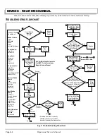
Fig. 25 Setting Adjuster Screw
New Brake Shoes
Screw Adjusting Screw In
Until 1 - 2 Threads Are Exposed
Existing Brake Shoes
Adjust 'in' 10 - 15 'clicks' (Minimum of
1 - 2 Threads Must Be Exposed)
Fig. 26 Brake Cable, Equalizer and Compensator
Spherical
Nut
Jam
Lock
Nut
Equalizer
Bracket
Compensator
Assembly
Cotter
Pin
Clevis
Pin
Brake
Cables
Compensator
Rod
Summary of Contents for MPT 800
Page 6: ...Page iv Repair and Service Manual TABLE OF CONTENTS Notes...
Page 10: ...Repair and Service Manual SAFETY INFORMATION Page viii Notes...
Page 12: ...GENERAL INFORMATION ROUTINE MAINTENANCE Page A ii Repair and Service Manual Notes...
Page 20: ...SAFETY Page B ii Repair and Service Manual Notes...
Page 32: ...BODY Page C ii Repair and Service Manual Notes...
Page 42: ...WHEELS AND TIRES Page D ii Repair and Service Manual Notes...
Page 46: ...FRONT SUSPENSION AND STEERING Page E ii Repair and Service Manual Notes...
Page 104: ...MOTOR Page G ii Repair and Service Manual Notes...
Page 112: ...BATTERIES AND CHARGING Page H ii Repair and Service Manual Notes...
Page 122: ...ELECTRICAL SYSTEM Page J ii Repair and Service Manual Notes...
Page 158: ...BATTERY CHARGER Page L ii Repair and Service Manual Notes...
Page 166: ...REAR SUSPENSION Page M ii Repair and Service Manual Notes...
Page 170: ...REAR AXLE Page N ii Repair and Service Manual Notes...
Page 176: ...WEATHER PROTECTION Page P ii Repair and Service Manual Notes...
Page 182: ...PAINT Page Q ii Repair and Service Manual Notes...
Page 186: ...TROUBLESHOOTING Page R ii Repair and Service Manual Notes...
Page 192: ...LIGHTNING PROTECTION AND GROUNDING Page S ii Repair and Service Manual Notes...
Page 198: ...GENERAL SPECIFICATIONS Page T ii Repair and Service Manual Notes...
Page 210: ...Page T 12 Repair and Service Manual GENERAL SPECIFICATIONS...


