


ELECTRONIC SPEED CONTROL (36V)
Page F-16
Repair and Service Manual
Read all of Section B and this section before attempting any procedure. Pay particular attention to all Notes, Cautions and Warnings
CONTROLLER REPLACEMENT
Tool List
Qty. Required
Socket, 3/8", 3/8" drive ................................................ 1
Socket, 7/16", 3/8" drive .............................................. 1
Socket, 1/2", 3/8" drive ................................................ 1
Ratchet, 3/8" drive ....................................................... 1
Extension, 6", 3/8" drive .............................................. 1
Insulated wrench, 9/16" ............................................... 1
Shop towel................................................................... 1
Torque wrench, 3/8" drive, in. lbs. ............................... 1
Torque wrench, 3/8" drive, ft. lbs. ................................ 1
Large screwdriver........................................................ 1
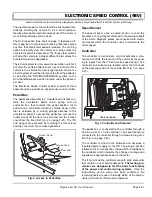
Remove the seat.
To prev ent electrical
shock, the BL- wire must
be removed before dis-
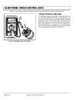
charging the controller by shorting the B+ and B- ter-
minals of the controller with a large screwdriver. Be
sure to hold screwdriver by the insulated portion.
Using an insulated wrench, remove the BL- wire from the
battery and cover the direction selector switch with a
shop towel.
Remove the environmental cover.
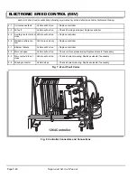
Note the location of the wiring on the controller
before removing wiring from controller (Ref
Fig. 2 on page F-1).
Remove the controller mounting bolts and remove the
controller
.
Mount new controller and reconnect wiring. Tighten the
controller mounting bolts to 108 - 132 in. lbs. (12 - 15
Nm) torque and the terminal bolts to 11 - 14 ft. lbs. (15 -
19 Nm) torque.
Replace the environmental cover and tighten the mount-
ing bolts to 108 - 132 in. lbs. (12 - 15 Nm) torque.
Reconnect the BL- battery cable and replace the seat.
SOLENOID REPLACEMENT
Tool List
Qty. Required
Socket, 3/8", 3/8" drive ................................................ 1
Socket, 7/16", 3/8" drive .............................................. 1
Socket, 1/2", 3/8" drive ................................................ 1
Ratchet, 3/8" drive .......................................................1
Extension, 6", 3/8" drive .............................................. 1
Insulated wrench, 9/16" ............................................... 1
Shop towel................................................................... 1
Torque wrench, 3/8" drive, in. lbs................................. 1
Torque wrench, 3/8" drive, ft. lbs. ................................ 1
Large screwdriver ........................................................ 1
Remove the seat.
To prev ent ele ctrica l
shock, the BL- wire must
be removed before dis-
charging the controller by shorting the B+ and B- ter-
minals of the controller with a large screwdriver. Be
sure to hold screwdriver by the insulated portion.
Using an insulated wrench, remove the BL- wire from the
battery and cover the direction selector switch with a
shop towel.
Remove the environmental cover.
Note the location of the wiring on the solenoid
before removing wiring from solenoid (Ref Fig.
2 on page F-1).
Remove the solenoid mounting bolts and remove the
solenoid
.
Mount new solenoid and reconnect wiring. Tighten the
solenoid mounting nuts to 68 - 82 in. lbs. (8 - 9 Nm)
torque, the #10 terminal nuts to 15 - 20 in. lbs. (2 Nm)
and the 5/16" terminal nuts to 50 - 55 in. lbs (6 Nm)
torque.
Replace the environmental cover and tighten the mount-
ing bolts to 108 - 132 in. lbs. (12 - 15 Nm) torque.
Reconnect the BL- battery cable and replace the seat.
!
!
!
!
Summary of Contents for MPT 800
Page 6: ...Page iv Repair and Service Manual TABLE OF CONTENTS Notes...
Page 10: ...Repair and Service Manual SAFETY INFORMATION Page viii Notes...
Page 12: ...GENERAL INFORMATION ROUTINE MAINTENANCE Page A ii Repair and Service Manual Notes...
Page 20: ...SAFETY Page B ii Repair and Service Manual Notes...
Page 32: ...BODY Page C ii Repair and Service Manual Notes...
Page 42: ...WHEELS AND TIRES Page D ii Repair and Service Manual Notes...
Page 46: ...FRONT SUSPENSION AND STEERING Page E ii Repair and Service Manual Notes...
Page 104: ...MOTOR Page G ii Repair and Service Manual Notes...
Page 112: ...BATTERIES AND CHARGING Page H ii Repair and Service Manual Notes...
Page 122: ...ELECTRICAL SYSTEM Page J ii Repair and Service Manual Notes...
Page 158: ...BATTERY CHARGER Page L ii Repair and Service Manual Notes...
Page 166: ...REAR SUSPENSION Page M ii Repair and Service Manual Notes...
Page 170: ...REAR AXLE Page N ii Repair and Service Manual Notes...
Page 176: ...WEATHER PROTECTION Page P ii Repair and Service Manual Notes...
Page 182: ...PAINT Page Q ii Repair and Service Manual Notes...
Page 186: ...TROUBLESHOOTING Page R ii Repair and Service Manual Notes...
Page 192: ...LIGHTNING PROTECTION AND GROUNDING Page S ii Repair and Service Manual Notes...
Page 198: ...GENERAL SPECIFICATIONS Page T ii Repair and Service Manual Notes...
Page 210: ...Page T 12 Repair and Service Manual GENERAL SPECIFICATIONS...


