


BATTERIES AND CHARGING
Page H-2
Repair and Service Manual
Read all of Section B and this section before attempting any procedure. Pay particular attention to all Notes, Cautions and Warnings
charger to a vehicle that is to be unattended
beyond the normal charging cycle. Over-
charging could cause damage to the vehicle
batteries and result in extreme overheating.
The charger should be checked after 24
hours and unplugged after the charge cycle
is complete.
Before charging the batteries, inspect the plug of the bat-
tery charger and vehicle receptacle housing for dirt or
debris.
Charge the batteries after each days use.
Monthly
•
Inspect all wiring for fraying, loose terminations,
corrosion or deterioration of insulation.
•
Check that the electrolyte level is correct and add
suitable water as required.
•
Clean the batteries and wire terminations.
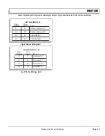
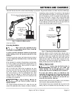
Electrolyte Level and Water
The correct level of the electrolyte is
1/2" (13 mm) above
the plates in each cell (Ref Fig. 1 on page H-2)
.
This level will leave approximately 1/4" - 3/8" (6 - 10 mm)
of space between the electrolyte and the vent tube. The
electrolyte level is important since
any portion
of the
plates exposed to air will be ruined beyond repair. Of
equal importance is too much water which will result in
electrolyte being forced out of the battery due to gassing
and the increase in volume of the electrolyte that results
from the charging cycle.
Do not overfill batteries. The
charging cycle will expel electro-
lyte and result in component damage.
A battery being charged will ‘gas’ with the majority of the
gassing taking place at the end of the charging cycle.
This gas is hydrogen which is lighter than air. Water and
sulfuric acid droplets will be carried out of the battery
vents by the hydrogen gas; however, this loss is minimal.
If the battery electrolyte level is too high, the electrolyte
will block the vent tube and the gas will
force
it out of the
vent tube and battery cap. The water will evaporate but
the sulfuric acid will remain where it can damage vehicle
components and the storage facility floor. Sulfuric acid
loss will weaken the concentration of acid within the elec-
trolyte and reduce the life of the battery.
Over the life of the battery, a considerable amount of
water is consumed. It is important that the water used be
pure and free of contaminants that could reduce the life
of the battery by reducing the chemical reaction. The
water must be distilled or purified by an efficient filtration
system. Water that is not distilled should be analyzed
and if required, filtration installed to permit the water to
meet the requirements of the water purity table (Ref Fig.
2 on page H-2).
Even if the water is colorless, odorless, tasteless and fit
for drinking, the water should be analyzed to see that it
does not exceed the impurity levels specified in the table.
Automatic watering devices such as the one included in
the Battery Maintenance Kit (P/N 25587-G01) can be
used with an approved water source (Ref Fig. 3 on page
H-3). These watering devices are
fast and accurate
to
use and maintain the correct electrolyte level within the
battery cells.
The watering device should only be used if the
electrolyte level is less than 1/2" (13 mm)
Fig. 1 Correct Electrolyte Level
Vent Cap
1/4" to 3/8"
(6 to 10 mm)
Plates
1/2" (13 mm)
Vent
Gas Vent
Expansion
Space
Electrolyte level should be
at least 1/2" (13 mm) above
the plates and 1/4" to 3/8"
(6 to 10 mm) below vent
Impurity
Parts Per
Million
Color ................................................................................Clear
Suspended ..................................................................... Trace
Total Solids....................................................................... 100
Calcium & Magnesium Oxides .......................................... 40
Iron ..................................................................................... 5
Ammonia ............................................................................ 8
Organic & Volatile Matter................................................... 50
Nitrites ................................................................................ 5
Nitrates .............................................................................. 10
Chloride .............................................................................. 5
Fig. 2 Water Purity Table
Summary of Contents for MPT 800
Page 6: ...Page iv Repair and Service Manual TABLE OF CONTENTS Notes...
Page 10: ...Repair and Service Manual SAFETY INFORMATION Page viii Notes...
Page 12: ...GENERAL INFORMATION ROUTINE MAINTENANCE Page A ii Repair and Service Manual Notes...
Page 20: ...SAFETY Page B ii Repair and Service Manual Notes...
Page 32: ...BODY Page C ii Repair and Service Manual Notes...
Page 42: ...WHEELS AND TIRES Page D ii Repair and Service Manual Notes...
Page 46: ...FRONT SUSPENSION AND STEERING Page E ii Repair and Service Manual Notes...
Page 104: ...MOTOR Page G ii Repair and Service Manual Notes...
Page 112: ...BATTERIES AND CHARGING Page H ii Repair and Service Manual Notes...
Page 122: ...ELECTRICAL SYSTEM Page J ii Repair and Service Manual Notes...
Page 158: ...BATTERY CHARGER Page L ii Repair and Service Manual Notes...
Page 166: ...REAR SUSPENSION Page M ii Repair and Service Manual Notes...
Page 170: ...REAR AXLE Page N ii Repair and Service Manual Notes...
Page 176: ...WEATHER PROTECTION Page P ii Repair and Service Manual Notes...
Page 182: ...PAINT Page Q ii Repair and Service Manual Notes...
Page 186: ...TROUBLESHOOTING Page R ii Repair and Service Manual Notes...
Page 192: ...LIGHTNING PROTECTION AND GROUNDING Page S ii Repair and Service Manual Notes...
Page 198: ...GENERAL SPECIFICATIONS Page T ii Repair and Service Manual Notes...
Page 210: ...Page T 12 Repair and Service Manual GENERAL SPECIFICATIONS...


