


FRONT SUSPENSION AND STEERING
Page E-4
Repair and Service Manual
Read all of Section B and this section before attempting any procedure. Pay particular attention to all Notes, Cautions and Warnings
To hold threaded tube while loosening jam nut,
use a wrench on the center, flat section of tube.
The tie rod has different threads on each end. The end with the
flat area on the threaded tube has left hand threads (clockwise
to loosen) while the end without the flat has conventional right
hand threads (counter-clockwise to loosen).
To adjust wheel alignment, loosen tie rod jam nuts (1)
and turn tie rod (2) until correct alignment is achieved.
Tighten jam nuts to 36 - 40 ft. lbs. (49 - 54 Nm) torque.
Test drive vehicle and confirm steering wheel is correctly
centered. If it is not centered, disconnect intermediate
shaft from steering shaft and center steering wheel (Ref
Fig. 5 on page E-4). Reconnect intermediate shaft and
tighten bolt to 155 - 215 in. lbs. (180 - 250 kg cm) torque.
Fig. 4 Wheel Alignment
X
Rear
X
Front
1/8" (3 mm)
0" (0 mm)
-
+
2
1
1
View from Underside
of Vehicle
Front of Vehicle
Fig. 5 Disconnect Intermediate Shaft to
Center Steering Wheel
Intermediate
Shaft
Remove Bolt
Summary of Contents for MPT 800
Page 6: ...Page iv Repair and Service Manual TABLE OF CONTENTS Notes...
Page 10: ...Repair and Service Manual SAFETY INFORMATION Page viii Notes...
Page 12: ...GENERAL INFORMATION ROUTINE MAINTENANCE Page A ii Repair and Service Manual Notes...
Page 20: ...SAFETY Page B ii Repair and Service Manual Notes...
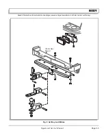
Page 32: ...BODY Page C ii Repair and Service Manual Notes...
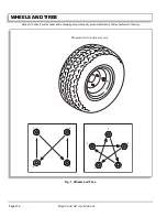
Page 42: ...WHEELS AND TIRES Page D ii Repair and Service Manual Notes...
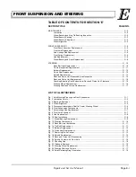
Page 46: ...FRONT SUSPENSION AND STEERING Page E ii Repair and Service Manual Notes...
Page 104: ...MOTOR Page G ii Repair and Service Manual Notes...
Page 112: ...BATTERIES AND CHARGING Page H ii Repair and Service Manual Notes...
Page 122: ...ELECTRICAL SYSTEM Page J ii Repair and Service Manual Notes...
Page 158: ...BATTERY CHARGER Page L ii Repair and Service Manual Notes...
Page 166: ...REAR SUSPENSION Page M ii Repair and Service Manual Notes...
Page 170: ...REAR AXLE Page N ii Repair and Service Manual Notes...
Page 176: ...WEATHER PROTECTION Page P ii Repair and Service Manual Notes...
Page 182: ...PAINT Page Q ii Repair and Service Manual Notes...
Page 186: ...TROUBLESHOOTING Page R ii Repair and Service Manual Notes...
Page 192: ...LIGHTNING PROTECTION AND GROUNDING Page S ii Repair and Service Manual Notes...
Page 198: ...GENERAL SPECIFICATIONS Page T ii Repair and Service Manual Notes...
Page 210: ...Page T 12 Repair and Service Manual GENERAL SPECIFICATIONS...


