


BRAKES - REAR MECHANICAL
Page K-10
Repair and Service Manual
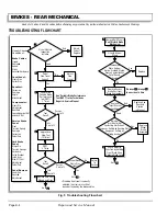
Read all of Section B and this section before attempting any procedure. Pay particular attention to all Notes, Cautions and Warnings
To prevent serious injury
or death from the use of
worn parking brake com-
ponents, do not attempt to re-new worn components.
The parking brake latch arm, kick-off cam and catch
bracket are hardened parts. Do not grind or file them
as doing so will cause the parts to lose their hardness
characteristics. New parts must be used.
10. Inspect catch bracket and latch arm.
Replace if showing signs of wear or damage (Ref Fig.
12 on page K-10).
11. Inspect the parking brake kick-off cam.
Look for wear and for correct adjustment. With the
parking brake engaged and fully latched, there must
be no gap between the top of the cam and the latch
arm. Adjust the kick-off cam (3) if required (Ref Fig.
12 on page K-10). It is very important that the correct
setscrews are used to hold the kick-off cam to the
pivot rod. Use of longer screws prevents correct
adjustment of pedal bumper (pedal travel) and may
prevent the brakes from adjusting properly.
12. Inspect kick-off cam linkage and bushings.
Check for wear and damage. The kick-off cam pivot
and bushings should move freely and be free of cor-
rosion. The kick-off cam should rotate when the
accelerator pedal is depressed.
Periodic Brake Performance Test (PBPT)
To prevent severe injury
or death resulting from
operating a vehicle with
improperly operating brake system, the braking sys-
tem must be properly maintained. All driving brake
tests must be done in a safe location with regard for
the safety of all personnel.
The Periodic Brake Performance Test (PBPT) should be
performed regularly (see Periodic Service Schedule in
the GENERAL INFORMATION AND ROUTINE MAIN-
TENANCE section of this manual) as an evaluation of
braking system performance. It is useful as a method of
identifying subtle loss of performance over time and as
part of troubleshooting a problem vehicle.
Before performing this test, inspect the brake pedal and
linkage and correct any problems found including adjust-
ing the brake pedal free travel if required.
The purpose of this test is to compare the braking perfor-
mance of the vehicle to the braking performance of new
or “known to be good” vehicles or to an established
acceptable stopping distance (see below). Actual stop-
ping distances will be influenced by weather conditions,
terrain, road surface condition, actual vehicle weight
(accessories installed) and vehicle speed. No specific
braking distance can be reliably specified. The test is
conducted by latching the parking brake to eliminate dif-
ferent pedal pressures and to include the affects of link-
age mis-adjustment. Significant changes or differences
in braking performance will be evident due to mis-adjust-
ment.
Establish the acceptable stopping distance by testing a
new or “known to be good” vehicle and recording the
stopping location or stopping distance. For fleets of vehi-
cles, several vehicles should be tested when new and
the range of stopping locations or distances recorded.
Over time, a subtle loss of performance may
take place; therefore, it is important to establish
the standard with a new vehicle.
Drive the vehicle at maximum speed on a flat, dry, clean,
paved surface (Ref Fig. 13 on page K-11). Quickly
depress the brake pedal to latch the parking brake at the
line or marker in the test area and remove foot from
pedal. The vehicle should stop aggressively. The wheel
brakes may or may not lock. Observe the vehicle stop-
Fig. 11 Parking Brake Pedal Hinge Inspection
Fig. 12 Kick-Off Cam Inspection
Torsion
Springs
Hinge
Pin
Push
Nut
!
!
Kick-Off
Cam
Set
Screw
Pedal Latch Arm
Catch
Bracket
Cam Must Be Against
Latch Arm At This Point
0.0" Gap
(0.0 mm)
!
!
Summary of Contents for MPT 800
Page 6: ...Page iv Repair and Service Manual TABLE OF CONTENTS Notes...
Page 10: ...Repair and Service Manual SAFETY INFORMATION Page viii Notes...
Page 12: ...GENERAL INFORMATION ROUTINE MAINTENANCE Page A ii Repair and Service Manual Notes...
Page 20: ...SAFETY Page B ii Repair and Service Manual Notes...
Page 32: ...BODY Page C ii Repair and Service Manual Notes...
Page 42: ...WHEELS AND TIRES Page D ii Repair and Service Manual Notes...
Page 46: ...FRONT SUSPENSION AND STEERING Page E ii Repair and Service Manual Notes...
Page 104: ...MOTOR Page G ii Repair and Service Manual Notes...
Page 112: ...BATTERIES AND CHARGING Page H ii Repair and Service Manual Notes...
Page 122: ...ELECTRICAL SYSTEM Page J ii Repair and Service Manual Notes...
Page 158: ...BATTERY CHARGER Page L ii Repair and Service Manual Notes...
Page 166: ...REAR SUSPENSION Page M ii Repair and Service Manual Notes...
Page 170: ...REAR AXLE Page N ii Repair and Service Manual Notes...
Page 176: ...WEATHER PROTECTION Page P ii Repair and Service Manual Notes...
Page 182: ...PAINT Page Q ii Repair and Service Manual Notes...
Page 186: ...TROUBLESHOOTING Page R ii Repair and Service Manual Notes...
Page 192: ...LIGHTNING PROTECTION AND GROUNDING Page S ii Repair and Service Manual Notes...
Page 198: ...GENERAL SPECIFICATIONS Page T ii Repair and Service Manual Notes...
Page 210: ...Page T 12 Repair and Service Manual GENERAL SPECIFICATIONS...


