


ELECTRONIC SPEED CONTROL (48V)
Page F-20
Repair and Service Manual
Read all of Section B and this section before attempting any procedure. Pay particular attention to all Notes, Cautions and Warnings
At monthly intervals, test the 48 volt system by allowing
the vehicle to roll down an incline with the accelerator
pedal released. Braking force should be felt at approxi-
mately 2 mph (3 kph) indicating that the 48 volt system is
functioning. If vehicle speed continues to rise, apply the
service brake to control speed and proceed with diagnos-
tic check.
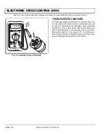
The 48 volt vehicle has the ability to diagnose and report
several common vehicle fault modes. These faults are
reported through a light emitting diode on the face of the
controller through a sequence of blinks.
The faults are reported as a series of blinks followed by a
pause and then another series of blinks. The number of
blinks in each series constitute the fault code. For exam-
ple: three short blinks followed by a pause, and then two
more short blinks would indicate fault code 3-2.
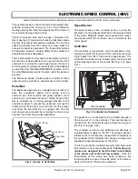
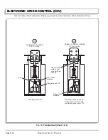
The two-position ‘Run-Tow/Maintenance’ switch is
located under the passenger seat (Ref Fig. 1 on page F-
20).
OPERATION
With the switch in ‘TOW/MAINTENANCE’ position:
•
the controller is deactivated
•
the electronic braking system is deactivated which
allows the vehicle to be towed or roll freely
•
the reverse warning beeper is deactivated
With the switch in ‘RUN’ position:
•
the controller is activated
•
the electronic braking system and reverse warning
beeper features are activated
48 volt vehicles operate only in the ‘RUN’ posi-
tion.
If all of the following events occur with the switch in ‘RUN’
position
a) the vehicle has been stopped for more than one
second
b) the accelerator pedal has been released for more
than one second
c) the vehicle begins to roll above 2 mph (3 kph)
the electronic braking will limit speed to approximately 2
mph (3 kph) and the warning beeper will sound. When
the accelerator pedal is depressed, the electronic brak-
ing and warning beeper will be overridden and normal
vehicle operation resumes. Any unusual situation sensed
by the 48 volt system will cause a similar response. The
system functions in all key switch positions.
The 48 volt system is not
a substitute for the ser-
vice brake which should
be used to control speed and reduce possibility of
injury.
If all of the following events occur with the switch in ‘RUN’
position
a) the vehicle is being driven down a slope
b) the vehicle speed exceeds the designed speed
with the accelerator pedal depressed or released
(except options equipped with compression brak-
ing)
the electronic braking will limit the speed of the vehicle to
the designed speed range (the warning beeper will not
sound). When the electronic braking system is activated
by this sequence of events, the motor generates power
which is returned to the batteries. 48 volt models are
equipped with a regenerative motor control system.
The motor’s speed is sensed and regulated directly by
the controller. As a vehicle begins to accelerate while
descending a hill, the speed sensor will cause the motor
to electrically retard the speed of the vehicle through
regenerative braking.
If the operator attempts to override the electronic braking
feature by moving the direction selector or key switch to
another position, the warning beeper will sound and the
vehicle will brake rapidly until it reaches the speed of
approximately 2 mph (3 kph).
The 48 volt system also incorporates an anti-stall protec-
tion feature that prevents commutator damage from stall-
ing the vehicle against an obstacle or ascending a hill.
Fig. 1 Run-Tow/Maintenance Switch
TOWING
MAINTENANC
E
Always select 'TOW / MAINTE
NANCE' position be
fore towing.
After reconnecting batteries
, allow a
minimum
of 30 seconds
before se
lecting '
RUN' positio
n
To disable ele
ctrical sys
tem place switc
h in 'TOW/MAINTENAN
CE'
position an
d remove battery wire.
Possibility o
f electrica
l arc a
nd battery
explosion.
Before re
moving/connecting batteries or
electrical
components
turn switch to 'TOW/MAINTENAN
CE' position.
RUN
TOW
MAINTEN
ANCE
WARN
ING
l
73340G01
Switch
!
!
Summary of Contents for MPT 800
Page 6: ...Page iv Repair and Service Manual TABLE OF CONTENTS Notes...
Page 10: ...Repair and Service Manual SAFETY INFORMATION Page viii Notes...
Page 12: ...GENERAL INFORMATION ROUTINE MAINTENANCE Page A ii Repair and Service Manual Notes...
Page 20: ...SAFETY Page B ii Repair and Service Manual Notes...
Page 32: ...BODY Page C ii Repair and Service Manual Notes...
Page 42: ...WHEELS AND TIRES Page D ii Repair and Service Manual Notes...
Page 46: ...FRONT SUSPENSION AND STEERING Page E ii Repair and Service Manual Notes...
Page 104: ...MOTOR Page G ii Repair and Service Manual Notes...
Page 112: ...BATTERIES AND CHARGING Page H ii Repair and Service Manual Notes...
Page 122: ...ELECTRICAL SYSTEM Page J ii Repair and Service Manual Notes...
Page 158: ...BATTERY CHARGER Page L ii Repair and Service Manual Notes...
Page 166: ...REAR SUSPENSION Page M ii Repair and Service Manual Notes...
Page 170: ...REAR AXLE Page N ii Repair and Service Manual Notes...
Page 176: ...WEATHER PROTECTION Page P ii Repair and Service Manual Notes...
Page 182: ...PAINT Page Q ii Repair and Service Manual Notes...
Page 186: ...TROUBLESHOOTING Page R ii Repair and Service Manual Notes...
Page 192: ...LIGHTNING PROTECTION AND GROUNDING Page S ii Repair and Service Manual Notes...
Page 198: ...GENERAL SPECIFICATIONS Page T ii Repair and Service Manual Notes...
Page 210: ...Page T 12 Repair and Service Manual GENERAL SPECIFICATIONS...


