


MOTOR
Page G-4
Repair and Service Manual
Read all of Section B and this section before attempting any procedure. Pay particular attention to all Notes, Cautions and Warnings
Remove brushes and replace with new brush replace-
ment kit. Locate springs against the side of each brush.
Install terminals and brush plate using reverse order of
removal. Install armature (commutator end) through
brush plate and press into new bearing using moderate
heat to aid installation. Position brushes against commu-
tator. Ensure the springs are seated against the rear of
the brushes and are able to move freely.
Motor Assembly
Tool List
Qty. Required
Socket, 3/8", 3/8" drive ................................................ 1
Torque wrench, in. lbs., 3/8" drive ............................... 1
Align the commutator end cover with the holes in the
motor housing and assemble (Ref Fig. 3 on page G-2).
Secure the commutator end cover to the motor housing
with bolts (2) and tighten to 90 in. lbs. (10 Nm) torque.
For non PDS motors, install bearing cap (1). For PDS
vehicles, attach ring magnet to armature shaft with
screw. Install inner snap ring in cover and insert speed
sensor. Secure with second snap ring (Ref Fig. 3 on
page G-2).
Motor Tests
The motor housing is not available as an individual part.
No testing is recommended to determine the specific
area of failure. When a test of the power wiring system
indicates that the system is operating correctly and the
vehicle either does not run or runs poorly, the motor is
the only remaining component and must be replaced.
Motor Installation
Tool List
Qty. Required
Socket, 7/16", 3/8" drive .............................................. 1
Torque wrench, in. lbs., 3/8" drive ............................... 1
Be sure that a bumper spline is installed between the
motor input pinion shaft and splines. Apply a small quan-
tity of molybdenum grease to the male portion of the
spline. Carefully mate the motor spline with the input
shaft of the rear axle. Align the orientation marks and
install the mounting hardware. Tighten to 168 in. lbs. (19
Nm) torque (Ref Fig. 2 on page G-1).
Attach the four motor wires to motor (Ref Fig. 6 on page
G-5) (Ref Fig. 7 on page G-5). Tighten the nuts to 66 in.
lbs. (7 Nm) torque.
On 48 volt model motors, tighten speed sensor magnet
attachment screw (17) to 18 - 23 in. lbs. (2 Nm) torque
(Ref Fig. 3 on page G-2).
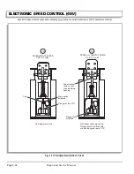
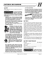
Fig. 4 Brush Wear
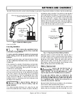
Fig. 5 Securing Brushes
.62" Min
(16 mm)
1.30"
(33 mm)
New Brush
Worn Brush
(Replace)
Brush
Brush
Spring
Spring Position
for Installed Brushes
Spring Position for
Removing/Replacing
Brushes
Brush
Summary of Contents for MPT 800
Page 6: ...Page iv Repair and Service Manual TABLE OF CONTENTS Notes...
Page 10: ...Repair and Service Manual SAFETY INFORMATION Page viii Notes...
Page 12: ...GENERAL INFORMATION ROUTINE MAINTENANCE Page A ii Repair and Service Manual Notes...
Page 20: ...SAFETY Page B ii Repair and Service Manual Notes...
Page 32: ...BODY Page C ii Repair and Service Manual Notes...
Page 42: ...WHEELS AND TIRES Page D ii Repair and Service Manual Notes...
Page 46: ...FRONT SUSPENSION AND STEERING Page E ii Repair and Service Manual Notes...
Page 104: ...MOTOR Page G ii Repair and Service Manual Notes...
Page 112: ...BATTERIES AND CHARGING Page H ii Repair and Service Manual Notes...
Page 122: ...ELECTRICAL SYSTEM Page J ii Repair and Service Manual Notes...
Page 158: ...BATTERY CHARGER Page L ii Repair and Service Manual Notes...
Page 166: ...REAR SUSPENSION Page M ii Repair and Service Manual Notes...
Page 170: ...REAR AXLE Page N ii Repair and Service Manual Notes...
Page 176: ...WEATHER PROTECTION Page P ii Repair and Service Manual Notes...
Page 182: ...PAINT Page Q ii Repair and Service Manual Notes...
Page 186: ...TROUBLESHOOTING Page R ii Repair and Service Manual Notes...
Page 192: ...LIGHTNING PROTECTION AND GROUNDING Page S ii Repair and Service Manual Notes...
Page 198: ...GENERAL SPECIFICATIONS Page T ii Repair and Service Manual Notes...
Page 210: ...Page T 12 Repair and Service Manual GENERAL SPECIFICATIONS...


