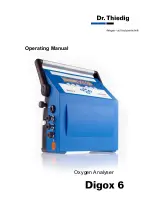
Dr.Thiedig Digox 6 Operating Manual Download Page 6


6


The instructions at hand are intended to make you 

familiar with the functions of the 

Digox 6

 analyser 

and to properly operate the device.  


The unit should be operated by trained personnel 

only. 


The operating manual contains the following 

additional information: 


  WARNING!


This indicates a warning note to avoid improper 

operating states of the unit. 


NOTE: 

Here you get further information and details. 


You should always place this operating manual 

within reach of the location of the 

Digox

.  

Due to technical improvements, some descriptions 

and figures in this operating manual may slightly 

differ from the functions of your 

Digox

 unit. 

Therefore, no claims can be made on the grounds 

of data, figures and descriptions included in this 

manual. 


Copyright


All rights for this operating manual are reserved by 

Dr. T Co.  


No part of this operating manual may be 

reproduced or distributed or used for competitive 

purposes or disclosed to third parties. 


In case of questions regarding the 

Digox 6


analyser, please contact: 


Dr. T Co. 

Service phone: 

(+49) 30 49 77 69-42


email: [email protected] 

Summary of Contents for Digox 6

Page 1: ...Operating Manual Oxygen Analyser...

Page 2: ...nzenallee 78 79 D 13357 Berlin Phone 49 30 49 77 69 0 Fax 49 30 49 77 69 25 E mail info thiedig com www thiedig com Service hotline 49 30 49 77 69 42 File O2 EC6 E 060301 doc Edition O2 EC D 01 03 06...

Page 3: ...lution 16 3 2 Connections 17 3 3 Taking the unit into service 17 4 Calibration of the Digox 6 18 4 1 Introduction 18 4 2 Variables influencing calibration 20 4 2 1 Flow 20 4 2 2 Pressure 20 4 2 3 Temp...

Page 4: ...3 4 1 The online data logger 34 5 3 4 2 Reading out the data storage in the Digox 6 35 5 3 4 3 Evaluate measuring data 36 5 3 5 Further DigoxWin functions 37 6 Maintenance 38 6 1 Cleaning the electro...

Page 5: ...al data Digox 6 51 10 Appendix 52 10 1 Definition of terms 52 10 2 Scope of supply with accessories kit 53 10 3 Spare parts 54 10 3 1 Analyser block Digox 6 54 10 3 2 Further spare parts 56 10 4 Digox...

Page 6: ...ual within reach of the location of the Digox Due to technical improvements some descriptions and figures in this operating manual may slightly differ from the functions of your Digox unit Therefore n...

Page 7: ...7...

Page 8: ...races operates according to the potentiostatic 3 electrodes measuring system developed by Prof T dt and Dr Teske The principle is based on an electrochemical reduction of dissolved oxygen at the measu...

Page 9: ...tomatically enable a safe allocation of measurement and measuring points In addition when using the special user TouchKeys a clear allocation of user and measurement is ensured In the created data fil...

Page 10: ...e flow 2 Moisture indicator for housing interior 3 Socket for RS 232 interface or Touch Memory Stick optional 4 Sample out flow Out 5 Socket for recorder output measuring range identification 6 Socket...

Page 11: ...11 Figure 1 3 1 Display 2 Sample supply In Figure 1 4 1 6 1 2...

Page 12: ...the Digox 6 off press and hold the key for 5 seconds 3 to switch the measuring mode on 4 to open the calibration menu 5 to confirm your input 6 Press this key once to switch the display lighting on a...

Page 13: ...13 Notes...

Page 14: ...re 2 1 1 Faulty parameter 2 Measuring value 3 Sample temperature in C 4 Flow in l h 5 Date and time 2 2 Calibration menu To enter press Figure 2 2 Selection of the calibration mode Thiedig active cali...

Page 15: ...The default setting is 9999 2 4 Menu level 2 Confirm the last entry in the main menu with Figure 2 4 Select numbers with or mark the next digit with Press to confirm the code Menu level 2 is opened H...

Page 16: ...he KCl solution In order to fill the reference cell the analyser block has to be dismantled Removal of analyser block 1 Lie the analyser flat on a table with the reverse side showing upwards 2 Loosen...

Page 17: ...tions clutches or other hose adapters are used air bubbles could settle on it Because of this the running in time of the analyser is prolonged in order to reach low concentrations WARNING Only use oxy...

Page 18: ...used to determine the calibration function With the essential requirement no oxygen no measuring current the processor places this function through the zero point Figure 4 1 The Thiedig active calibra...

Page 19: ...s with the sampling device The short calibration is especially suitable for cases in which constant measuring conditions for a calibration are only available for a short time Measurement in wort If th...

Page 20: ...ent of 3 per C The Digox 6 has got a temperature compensation in the range between 0 and 50 C 4 3 Calibrating of the flowmeter The calibration of the flowmeter is done in the works with water When tak...

Page 21: ...liquid collected Press or to select a number Press to mark the next digit 5 Use to confirm your input Figure4 3 WARNING The value to be entered should be between 150ml and 180ml If a wrong value is e...

Page 22: ...carried out with a flow between 9 1 and 10 9 l h After connecting the unit to the sampling point let run down the oxygen value first Only Start the calibration if the values of the temperature and of...

Page 23: ...d flow are examined during calibration Figure 4 11 A comparison shows no deviation the newly calculated Ks factor is displayed Figure 4 12 Figure 4 12 A comparison shows a deviation please refer to fa...

Page 24: ...the short calibration possible changes in oxygen concentration flow and temperature are not examined during the calibration The short calibration takes 45 seconds NOTE The calibration must be carried...

Page 25: ...s 43s 0s The calibration current produces a defined amount of oxygen in the sample 3 After successful calibration the calculated Ks factor is displayed for 3 seconds Figure 4 15 4 Then the Digox 6 aut...

Page 26: ...er to section 8 1 4 6 1 Ref min calibration 1 Press The calibration menu is opened 2 Press and hold until the menu item REF MIN CALIBRATION is highlighted Confirm with Figure 4 16 3 A selection menu a...

Page 27: ...rt the calibration Figure 4 20 4 The calibration starts A countdown appears beginning with 50 seconds After the calibration a reference concentration is polled Use the cursor keys to enter it and conf...

Page 28: ...0 C Maximum 50 C Threshold value 70 C Threshold value 110 C Special edition The temperature is compensated electronically within the limits stated If this temperature is exceeded it will lead to damag...

Page 29: ...he amount of recorded values the data logger can be started three times If the total amount of recorded measuring values is attained the measurement will be stopped and a message will be displayed ple...

Page 30: ...R To stop the data logger press to confirm The data logger has already recorded three series of measurement A new start of the logger is possible only after deleting the data please see hint section 5...

Page 31: ...ATA LOGGER Now the measuring values will be read out from the data logger of the Digox 6 NOTE For using DigoxWin please read section 5 4 Displaying measuring values only measuring point data logger 1...

Page 32: ...from the file Digoxwin ini For this proceed as follows a Use your right mouse key to click on the file b Select Properties c Delete the tick read only 4 Use your right mouse button to click on the fil...

Page 33: ...nuous data logger of the Digox 6 Read out measuring points Read out the measuring point logger of the Digox 6 Active calibration Start active calibration in DigoxWin Settings Menu code Change the menu...

Page 34: ...splay Measuring at the Digox 6 3 Sampling interval for online measurement 5 10 15 20 25 30 seconds 4 Current data record number A maximum of 4 000 is possible if there are more than 4 000 DigoxWin wil...

Page 35: ...PC A corresponding message is faded in the DigoxWin program window 3 Then the transferred measuring data are displayed in DigoxWin as a table NOTE In order to read out data the Digox 6 must be switch...

Page 36: ...he extension xls and click the Save button to confirm the file name MS Excel will be opened and the measuring data will be transferred Figure 5 9 In Excel the measuring data can be displayed in tables...

Page 37: ...e Digox 6 Select medium Select interface and transfer rate see section 5 3 2 Change limits and alarms not available with the Digox 6 Click the Close button to exit the current menu Poll status message...

Page 38: ...the like water a brush for cleaning the counter electrodes included in the supply a tooth brush or the like recommended for cleaning the contact piece compressed air pistol if available WARNING Do no...

Page 39: ...ces are connected must be dry 6 2 Exchanging diaphragm and sealing rings Dr Thiedig Co recommends to annually change the diaphragm and all sealing rings at the analyser block 6 2 1 General hints To ex...

Page 40: ...7 mm socket spanner to loosen the 4 hex nuts 21 Withdraw the connection rods 19 The 5 single blocks are now separated from each other 6 Use the special screwdriver to remove the diaphragm 7 7 Loosen...

Page 41: ...dling of rechargeable battery An important element for measuring with the Digox 6 is the state of the battery The Digox 6 is equipped with an improved nickel metal hydrid battery NOTE The battery is a...

Page 42: ...he analyser block Open and clean the flowmeter If this does not work please contact our maintenance hotline The temperature is flashing in the left top of the display for example the display reads 49...

Page 43: ...DigoxWin version with regard to the Digox 6 firmware NOTE Always use the supplied software version with the respective analyser Display message EEPROM Error at Simultaneous operation of the continuou...

Page 44: ...es more than 5 with regard to the current measured between sec 0 and sec 5 Calibration error D The temperature measured in sec 20 deviates more than 5 with regard to the temperature measured in sec 0...

Page 45: ...45 Notes...

Page 46: ...the recorder output is displayed 8 2 Selecting recorder measuring ranges and output currents 1 In the main menu press until the menu item MEASURING RANGES is highlighted Press to open the menu MEASURI...

Page 47: ...ith a four digit code The default setting is 9999 It can be modified using the menu item GENERATE THE CODE Take care to remember the code It can also be changed in DigoxWin please refer to section 5 3...

Page 48: ...the contrast in steps between 0 and 100 Press to confirm your selection Figure 8 9 Checksum The checksum serves to check the device components before switching off Highlight the menu item and press Us...

Page 49: ...date Highlight the menu item and confirm with The setting mode is active Changes are made using the cursor keys Use to confirm After setting highlight the menu item RETURN and confirm with 8 3 4 Polli...

Page 50: ...8 3 7 Generating a code You can use this menu item to generate a new access code for menu level 2 NOTE If you have changed the access code and forgotten it it can be read out and changed again in Digo...

Page 51: ...Recorder output One output 0 4 20mA for concentration 0 1 000 mg l 0 20 00 mg l to be set to a fixed value or automatic changeover and detection of the measuring range IMPORTANT NOTE Connection of a r...

Page 52: ...f the level to a sudden concentration change Ambient temperature This is the temperature permitted in the environment where the unit is operated Sample temperature This is the temperature of the sampl...

Page 53: ...0 1 Replacement diaphragm DG 50 09 00 1 Sealing ring set Digox 5 6 DG 50 35 00 1 Test tube brush ZZ 19 00 40 1 Measuring cylinder 250ml ZZ 13 00 62 1 DigoxWin software TN 68 50 00 1 Interface cable DG...

Page 54: ...54 10 3 Spare parts 10 3 1 Analyser block Digox 6 Figure 10 1 Block parts Digox 6 Figure 10 2 Sealing rings Digox 6...

Page 55: ...lamping bolt top 21 XX 09 34 05 4 Hex nut 22 XX 01 25 06 4 Ring washer 23 DG 94 05 18 4 Pressure piece 24 DG 50 19 00 1 Temperature sensor 25 DG 50 25 40 1 Spindle with flange 26 DG 50 25 30 1 Output...

Page 56: ...luded in the service kit Digox 5 6 EC K 05 13 78 Euro adapter for charging unit ZZ 58 00 94 UK adapter for charging unit ZZ 58 00 95 US adapter for charging unit ZZ 58 00 96 Australian adapter for cha...

Page 57: ...57 10 5 Menu overview...

Page 58: ...D Socket Function Socket 1 Pin 1 Pin 3 RDO Pin 2 Pin 2 TDO Pin 3 Pin 5 GND Pin 4 RS 232 Touch Memory Pin 5 Touch Memory System Socket 2 Pin 1 Pin 2 Measuring range identification Pin 3 GND Analog Out...

Page 59: ...59 Notes...

Page 60: ...on 16 Kf factor 21 Ks factor 22 38 L Language 48 LCD contrast 48 M Main menu 15 Maintenance 38 Make system settings 48 Measurement in beer 19 Measurement in wort 19 Measuring 14 Measuring electrode 38...

Page 61: ...61 Touch Memory System 9 Troubleshooting 42 U Unit description 8 Unit extensions 56 Z Zero current 19 26...

Page 62: ...62 Dr Thiedig Co Prinzenallee 78 79 D 13357 Berlin Phone 49 30 49 77 69 0 Fax 49 30 49 77 69 25 Email info thiedig com www thiedig com Service Hotline 49 30 49 77 69 42...

Reviews: