56 / 96
10 Related Documents
10.1 General drawings with list of components
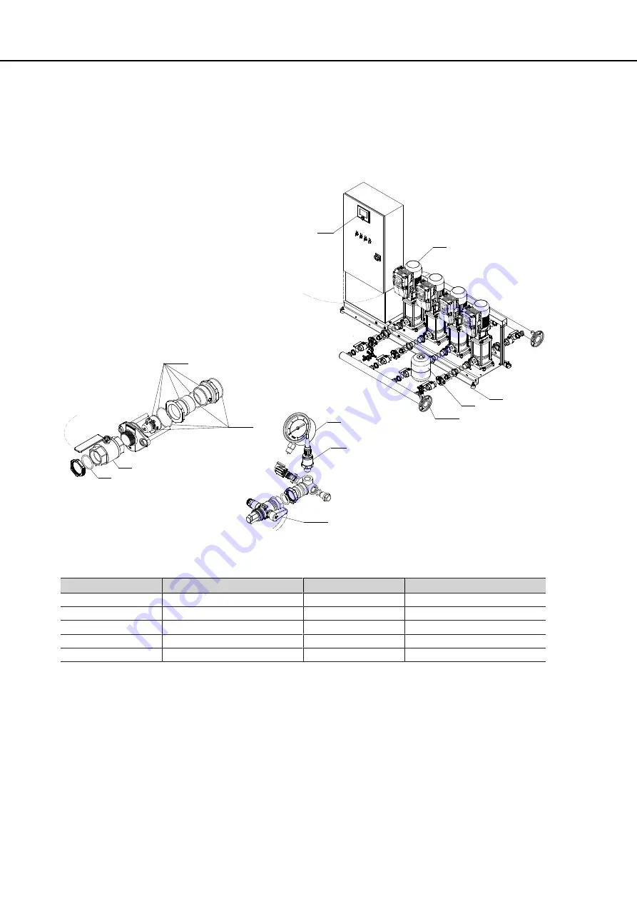
10.1.1 Hydro-Unit Utility Line with DPV 2, 4, 6, 10, 15
412
743
742.01
742.02
79-2
691
743.90
743.90
591
655
79-1
595
Fig. 21:
Utility Line F/VC/SVP with DPV 2, 4, 6, 10, 15
Table 23:
List of components
Part No.
Description
Part No.
Description
79-1
Automatic control unit
655
Pump
79-2
Measuring transducer
691
Pressure gauge
412
O-ring
742.01/.02
Lift check valve
591
Accumulator
743
Ball/plug valve
595
Anti-vibration pad
743.90
Ball valve
The individual parts of the pump set are shown in the product literature of the pump set.
Summary of Contents for Hydro-Unit Utility Line F
Page 29: ...29 96 1 2 Fig 12 PE connection 1 Earthing terminal 2 Location of power connection ...
Page 58: ...58 96 ...
Page 92: ...92 96 T Tank 79 Timers 73 W Warnings 9 Warranty claims 7 ...
Page 93: ......
Page 94: ......
Page 95: ......


