33 / 96
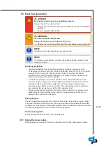
5.5 Electrical connection
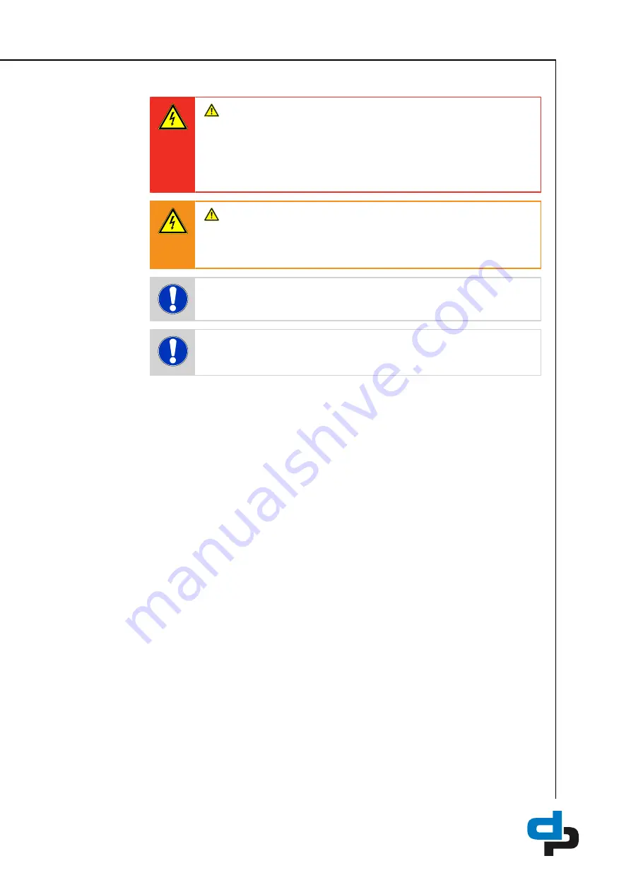
DANGER
Electrical connection work by unqualified personnel
Danger of death from electric shock!
Ø
Always have the electrical connections installed by a trained and qualified
electrician.
Ø
Observe regulations IEC 60364 .
WARNING
Incorrect connection to the mains
Damage to the power supply network, short circuit!
Ø
Observe the technical specifications of the local energy supply companies.
NOTE
Installing a motor protection device is recommended.
NOTE
If a residual current device is installed, observe the operating manual for the
frequency inverter.
Lightning protection
– Electrical installations must be protected against overvoltage (compulsory since
14 December 2018) (see DIN VDE 0100-443 (IEC60364-4-44:2007/A1:2015, modified)
and DIN VDE 0100-534 (IEC 60364-5-53:2001/A2:2015, modified). Whenever
modifications are made to existing installations, retrofitting a surge protective device
(SPD) in accordance with VDE is mandatory.
– A maximum cable length of 10 metres should not be exceeded between the surge
protective device (usually type 1, internal lightning protection) installed at the service
entrance and the equipment to be protected. For longer cables, additional surge
protective devices (type 2) must be provided in the sub-distribution board upstream of
the equipment to be protected or directly in the equipment itself.
– The associated lightning protection concept must be provided by the operator or by a
suitable provider commissioned by the operator. Surge protective devices can be
offered for the control units on request.
Wiring diagram
The wiring diagrams are located in the control cabinet, which is where they must be stored.
The product literature of the
switchgear and controlgear assembly
supplied with the system
includes a list of the electrical components installed. When ordering spare parts for electrical
components, always indicate the number of the wiring diagram.
Terminal assignment
For the terminal assignment refer to the wiring diagram.
5.5.1 Sizing the power cable
Determine the cross-section of the power cable based on the total rated power required.
Summary of Contents for Hydro-Unit Utility Line F
Page 29: ...29 96 1 2 Fig 12 PE connection 1 Earthing terminal 2 Location of power connection ...
Page 58: ...58 96 ...
Page 92: ...92 96 T Tank 79 Timers 73 W Warnings 9 Warranty claims 7 ...
Page 93: ......
Page 94: ......
Page 95: ......


